Also, you can see the mounting point for the forward roll bellcrank on the angled tube.
This weekend I didn't so much make progress so much as reveal progress that I'd made earlier but didn't notice.
I finally did a full installation of the platform assembly into the test pod. This involved bedding three phenolic pads into the pod with a polyester flox mixture, and then covering the pads over with two layers of bias-cut fiberglass. Once that was all hard, I placed the platform assembly onto the three pads and drilled the holes for the dozen countersunk screws that hold it all in place. Then I used a microstop countersink on the outside ends of the holes.
Once I had the platform mechanism installed, I did a build-up of all the cockpit parts to verify fitment. It all went together clean and easy, and feels good and solid. I haven't done the input force measurements yet, but I did pull and push on the stick as hard as I could while sitting in the cocpit, and I couldn't bend it, break it, or even make it complain.
At this point I feel confident enough about the cockpit components that I'll probably continue the program using my new HP-18 as the development article. I knew I'd have to do that some time, since I need a complete aircraft to validate the mid-fuselage parts of the installation. But switching over now means that things are going better than I'd originally expected.
Now the next thing for me to do is to retrieve my HP-18 from it's winter storage in Reno, and get it into the shop.
|
|
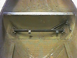
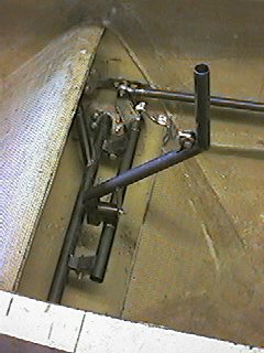
This photo shows the platform assembly mounted in the fuselage. |
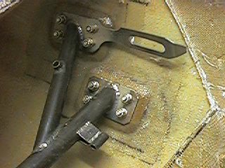
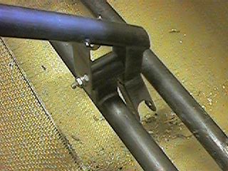
| Here you see platform assembly where it joins the fuselage pod on the right side. The thing with the long slot in it is the stop plate, which provides a hard stop at the ends of the available pitch input travel. |
|
|
|
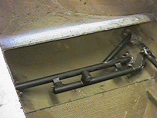
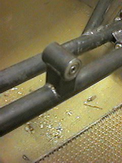
In this picture, the pitch carriage has been added to the platform. |
|
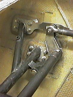
This is the right side of the assembly again, this time showing the pitch horn and the forward end of the pitch P-P tube. You can see how a bushing on the far side of the horn engages the slot in the stop plate. The bushing is attached with the same bolt as secures the rod end to the horn. Also, you can see the mounting point for the forward roll bellcrank on the angled tube. |
|
|
|
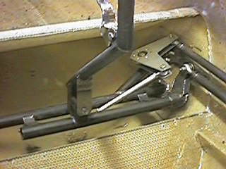
This is the stanchion and mount for the two KP-3 bearings that support the control stick, and allow it to pivot in roll. |
| Here we've added the control stick for perspective. |
|
|
|
This view shows how the stick attaches to the roll pivot. You can see the extension on the lower end of the control stick that attaches to the transverse roll pushrod. |
| This view pretty much shows the whole cockpit mechanism. We've added the forward roll bellcrank and transverse pushrod, and connected the main roll P-P tube. |
|
|
|
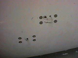
Here you are looking at the outside of the fuselage pod, where the eight countersunk screws attach the platform assembly to the inside of the pod. This one looks pretty messy, because there were some tooling holes there that I used when making the original jig tooling. Once the assembly is complete, you'd fill over the heads of these screws as is done for the screws that secure the tow hitch. |
page updated 04/02/01 all text and graphics copyright (c) 2001 HP Aircraft, LLC