The weekend before last I finally got over the hill into Reno to retrieve my HP-18, N86RS and get it into the shop.
This last weekend (24, 25 March 2001) I started the center stick installation in earnest. I removed the old instrument pod, removed the old side-stick mechanicals, and then did the installation steps shown in the following photos. Basically, in one long push I got N86RS up to the point where I left off with the test pod shown in the earlier photos.
In addition to the work in the photos, I also installed the modified mixer (with the different pitch input horn). I also installed the reinforcing angle that protects the mixer bracket from tearing out of the fiberglass bulkhead under the increased pitch loads imposed by the shorter input horn. That reinforcing angle ties the right mixer bracket in to the right aft landing gear pivot plate for better strength and stiffness.
Next weekend, it'll be time to mount the nylon guides for the two forward push-pull tube sections, and then work out the lengths for the aft push-pull tubes. I'll also finalize the geometry of the aft roll bellcrank, and do a wooden prototype for the jig for the aft roll bellcrank mounting tripod.
|
|
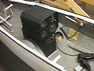
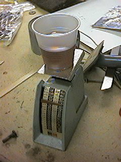
Here's the cockpit of N86RS, our flight test guinea pig for the center stick development project. The instrument pod in this ship is mounted fairly far aft on the knee hump. That feature put the instruments within easy reach of the pilot. Unfortunately, it also increases the interference between the instrument pod and the control stick. More on that topic in a later installment. |
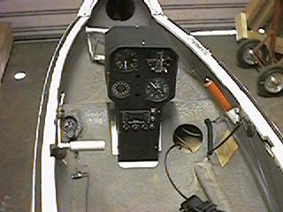
| Here's another view, this time showing the old A8A oxygen regulator mounted on the left side of the knee hump. Fortunately, the A8A is deactivated, and the ship uses a bottle-mounted Nelson regulator instead. I won't have to explore whether the A8A interferes with the center stick mechanism; I'll just shelve the A8A as a spare for the one in my HP-11. |
|
|
|
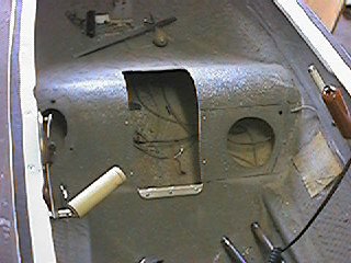
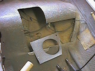
Here, I've removed the instrument pod to discover that the pod was installed in a big cutout in the knee hump. You can see the ink lines where I've marked out the additional cutout that I'll use to install the stick mechanism. This little cutout later proved to be still too small, so I'll probably be recommending a much bigger cutout (basically wall to wall) for future installations. |
|
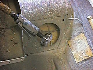
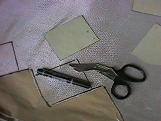
Here I've got my straight die-grinder set up with a cutoff wheel to cut along the ink line.
|
|
|
|
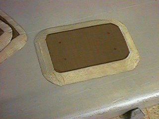
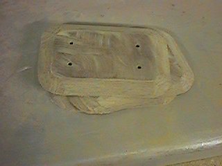
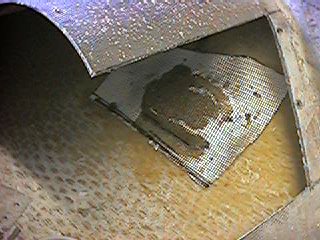
And here the cutout is done, allowing access to the under-hump area where the stick mechanism goes. |
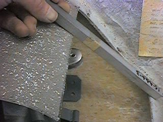
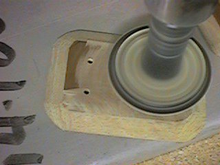
| Here I've got the platform assembly and roll bellcrank in place, and I'm moving the assembly around to find the right spot. The critical dimension is the clearance between the aft-pointing horn of the roll bellcrank and the inner surface of the hump. What I'm looking for here is about 3/8" clearance between the straight-edge and the tip of the bellcrank horn. |
|
|
|
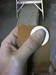
Here I'm using a big washer as a template to draw the 5/8" corner radius onto one of the 2-1/4" x 3-1/4" phenolic pad blanks. |
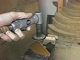
| And here I'm using my right-angle die-grinder with a coarse Roloc sanding disk to do the corner radius on the pad blank. |
|
|
|
Here I'm marking the outline and screw holes of the mounting plate on the phenolic pad. I'm using the scribe template for the plate here, but in a field installation you'd just use one of the mounting plates that are welded onto the platform assembly. |
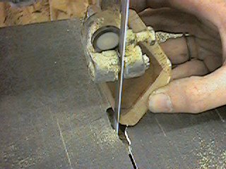
| Here I'm using the bandsaw to rough-out the edge bevel on the phenolic pad. This is a pretty dangerous stunt, and I don't recommend it. It's a lot safer to just use a file or a die-grinder to do the bevel. |
|
|
|
Here's the first pad after finishing the bevel off with the die grinder. All I did was to grind away on the pad until the slope of the bevel extended between the outline of the mounting plate and a knife-edge at the pad perimeter. |
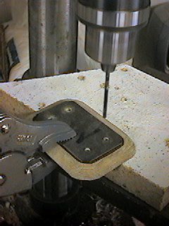
| Here I'm drilling 5/32" through the pad, using the scribe template as a drill guide. Again, you'd just use the mounting pads welded to the platform assembly as your guide. |
|
|
|
The final step in making the pads is to scuff away all of the shiny varnish on the top and bottom surfaces of every pad. Here I'm doing that with the sanding disk on my die-grinder. |
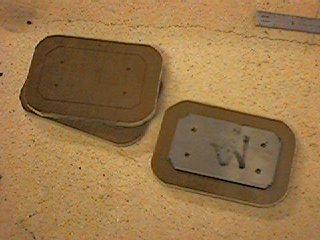
| And here's my three phenolic mounting pads, radussed, drilled, beveled, scuffed, and ready for some action. |
|
|
|
Here I'm preparing to temporarily mount all three pads onto the platform assembly, using a .025" aluminum shim to simulate the thickness of the fiberglass reinforcement that gets added later. In this shot, the phenolic pad doesn't show up very well because it's the same color as my fiberboard workbench. |
| Here's one of the phenolic pads temporarily mounted to the mounting plate with 1/4" long #6 sheetmetal screws. You can just barely see the shim between the pad and the mounting plate. |
|
|
|
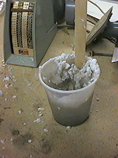
It's time for some gooey stuff! Here I've got my 16-ounce postage scale (yard sale price $.050) out, and I'm pouring out 2 ounces of resin. In a moment, I'll don my safety goggles and and catalyze the resin with 20 drops of MEKP. |
| With the catalyst in, the clock is hot and time is wasting. Here, I've dropped a big dollop of flocked cotton fibers (flox) into the cup, and am mixing it in with a popsicle stick. I mix it together thoroughly, adding more flox until it's the consistency of peanut butter. |
|
|
|
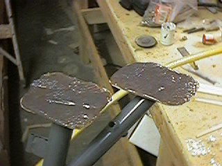
And here's two of the pads, freshly buttered with a nice uniform 1/8" thick layer of flox mixture. The one pad on the other end of the platform assembly is similarly buttered. |
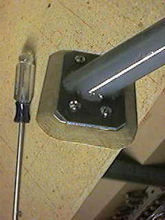
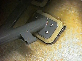
| And here I've got the platform assembly pressed into place on the marks I made earlier. Just before this step, I cleaned the mounting surface on the fuselage with MEK. Anyhow, I press the platform with the buttered pads in place, and then scrape away the squeeze-out using the rounded end of a popsicle stick. There was one place where there was no squeeze out, and that's where I deposited the flox that I scraped up. |
|
|
|
While waiting for the flox misture on the pads to cure, I'm using my paper templates to cut out the reinforcing patches. In order to drape well over the compound curves of the pad, the patches have to be cut with the fibers on the bias. That's why you see the saw-tooth pattern on my swatch of fiberglass cloth. |
| And here I'm starting to press the first patch into place. I started by painting a thin coat of resin over the area where the pad will go. Then I put the patch in place and stipple it down with an acid brush. I'm trying to not add more resin unless I really have to. So I stipple the patch down while brushing in just enough resin to wet out the cloth, but not enough resin to fill in the weave. That gives a good strong reinforcement, without interfering with the alignment of the pad and the mounting plate. Once the small patch is in place, I repeat the process for the larger patch. |
|
|
|
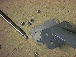
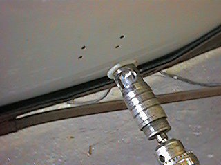
Here you can see that I've jumped ahead several steps without taking any photos. All the reinforcing patches are cured, and I've put the platform assembly in place and drilled the holes for the mounting screws. Now I've got my microstop countersink chucked up, and I'm getting ready to do more violence to the formerly-pristine exterior of the fuselage. |
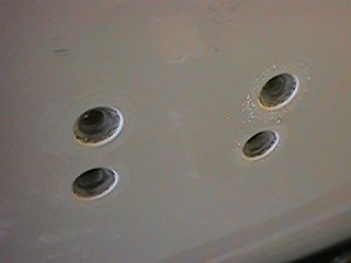
| And here, the microstop countersink has done its job. Here are four of the twelve countersunk holes for the MS24694 machine screws that hold the platform assembly in place inside the fuselage. |
|
page updated 04/02/01 all text and graphics copyright (c) 2001 HP Aircraft, LLC