I had some really good shop sessions over the Christmas holidays. I got a lot of stuff done, mostly jiggery for the center stick system. Monday morning (2 Jan 2001) I delivered four jigs to the welder for stuff to do this week. It includes the first -703 control stick handle, and a modification of the -702 pitch carriage. I'm shortening the right end of the carriage to leave more room for the slotted stop plate between the horn and the fuselage shell.
One thing I did was work out the mounting for a wheel brake handle to the stick. I'm having two little tabs welded onto the stick below the handle for the brake lever. The tabs are sized to accept the alloy handle for the Odessey Trigger mountain bike brake handle. I'm also having a 1/8" ID steel tube welded into the stick for the brake cable to the master cylinder. Using those welded-in provisions instead of the clamp supplied with the handle cuts down on the overall bulk of the brake handle installation, and lets me use a more compact control stick. Also, I think that the overall brake handle installation will look pretty slick, with it's combination of finely shaped alloy brake handle and welded-in mounting provisions.
I've also jigged out the modification to the mixer to make it accept the P-P tube from the stick mechanism, and also jigged out the two forward P-P tubes. The forward P-P tubes for both pitch and roll have ball-bearing rod ends at the forward end, and run in Nylon guide blocks near the seat back bulkhead. They both have forks welded onto them just aft of the guide blocks. The aft P-P tubes have plain rod ends at the forward end (where they meet the forks on the forward P-P tubes), and ball-bearing rod ends where they meet the horns for the pitch/yaw mixer and the roll bellcrank. That arrangement, with the forks on the P-P tubes that run in nylon guides, allows me to have the rod ends arranged so that they see no significant lateral loadings.
This weekend I also made a simple force scale, and calibrated it from 0 to 110 lbs in 10 lb increments using a bathroom scale. I used a compression coil spring from the hardware store, and a bunch of long bolts for guides.
The purpose of the force scale is to measure forces applied to the control stick in later phases of the development program. In those phases, we will validate that the control stick and it's mechanisms adequately support input forces that the pilot can be reasonably expected to apply.
The first time I calibrated the scale was somewhat of a disappointment. Everything went smoothly from 0 to about 120 lbs. But with about 130 lbs applied, the spring yielded a bunch and settled into the fully collapsed state, invalidating all of the calibration marks I'd made. However, when I recalibrated it twice after that to 110 lbs, it was consistent both times. So I made a new set of calibration marks to 110 lbs. I haven't measured the spread of the calibration marks, but they look very even and linear.
As to the reasonableness of using such a crude device to test the system input forces, I think that it will be OK so long as I can repeatably validate the calibration, and apply a reasonably conservative fudge factor. Force-measuring scales based on coil springs are generally very linear, and give a lot of bang for the buck in terms of reliability, repeatability, and accuracy.
Here are some photos of the latest shop adventures:
|
|
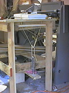
This is sort of a general overview of the rig I used to calibrate the force-measuring scale. The basic component is, of course, a bathroom scale of known accuracy. The bathroom scale is actuated by a loop of rope that comes up through holes in the workbench from the force scale. You can see the force scale anchored to the undercarriage of the workbench. The horizontal stick just below the tabletop is a 'spreader bar' that orients the rope vertically so that it does not touch the sides of the holes where it passes through the surface of the workbench. |
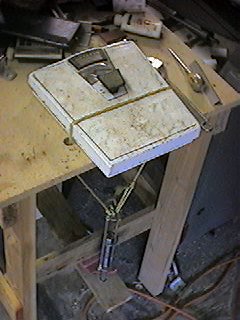
| Here you're looking at the bathroom scale that I used as a calibration device. In this photo, you see the rope just laid across the platform of the scale. Mindful that some folks say that bathroom scales tend to be sensitive to the even distribution of pressure, I also did a calibration run with the force distributed over the surface of the scale with a slab of 3/4" thick plywood. The force values came out about the same. |
|
|
|
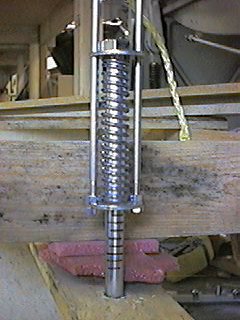
This is a closup of the force scale. You can see that it is a simple compression coil spring on a 5/8" bolt, with a pair of washers for guides. The calibration marks are applied to the 5/8" bolt right below the bottom guide. Each calibration mark represents 10 lbs of force. The calibration marks are initially applied with a marking pen, and are later scribed in with a die grinder after they are confirmed by a second calibration run. |
| Here you're looking at the third or fourth wooden dowel prototype for the control stick. The size and shape of the stick is based primarily on what happens to feel about right when I sit in the cockpit. There are several features that I didn't include on this prototype, notably the wheel brake handle and a mounting strut that attaches to the aft bearing on the longitudinal roll pivot. Those features will be present on the welded first-article items that I'm getting from the TIG welder this Friday. |
|
|
|
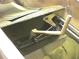
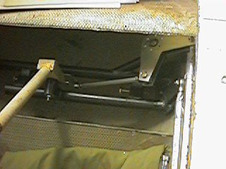
This is a view of the stick mechanism looking down from the right cockpit rail. You can see how the transverse roll pushrod attaches to the lower extension of the control stick, and also to the forward roll bellcrank. You can also see the slight lateral displacement between the pitch (lower) and roll (upper) push-pull tubes. |
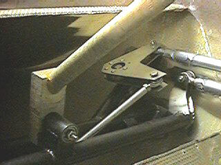
| Here you're looking beyond the control stick at what's going on at the right fuselage wall. What I tried (and failed) to show in this photo is the slotted stop plate just outboard of the horn on the pitch carriage. That stop plate is fixed to the upper left mounting plate on the platform assembly. The stop plate has a slot that is engaged by a flanged bushing on the pitch horn. The flanged bushing is fixed to the outboard end of the bolt that secures the rod-end to the horn. The slot in the stop plate limits the travel of the control stick. |
|
page updated 04/02/01 all text and graphics copyright (c) 2001 HP Aircraft, LLC