This weekend marks the beginning of the downhill slide into flight test. I did make another prototype of the aft roll bellcrank support tripod, and I have a one-time jig to take to the welder. I also sized the aft roll P-P tube and aft transverse pushrod.
I also got a lot of work done on the knee hump access cover and instrument pod provisions. I decided that the fastest way into the air was to make an aluminum access cover, and also to adapt the instrument pod that was originally in the aircraft.
The things I didn't get done this weekend are work on the roll anti-torque link, the P-P tube cover, and the gear counterbalance strut.
However, I did manage to get some more parts together for the double-geared flap crank that I'll be using. I also found a neat place to put the battery, now that the bottom of the instrument pedestal is occupied. I cut open the space just forward of the wheel well, and found enough room for the battery there.
Here are the photos:
|
|
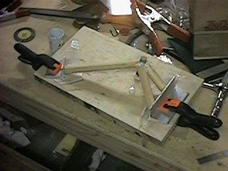
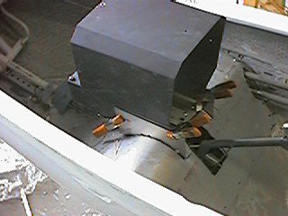
Here I'm making the jig for the aft roll bellcrank. This is actually a different design than the one I was working with last weekend. The earlier design required an extra hole in the rear spar carrythrough. This new one uses only existing bolt holes at the main and aft spar carrythroughs. |
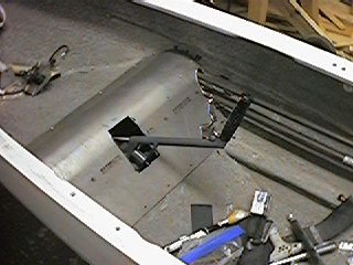
| And here's the tripod in position. I guess I'm going to need a bellcrank to hang there. |
|
|
|
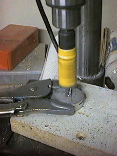
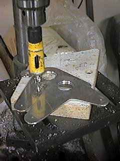
Here I'm making the spacer for the aft roll bellcrank. I used a 1-7/8" hole saw to produce a 1-3/4" disk from some 3/8" plate, and now I'm coring it with my 7/8" hole saw. And, yes, I often use Vise-Grips as a drill press vise. |
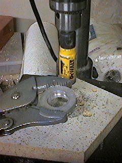
| Here's the finished spacer, ready for match drilling with the bellcrank bearing. |
|
|
|
Here I'm using that yellow 7/8" hole saw again, this time to drill the bearing holes in the bellcrank leaves. Notice that, unlike the forward roll bellcrank, the arms of the aft bellcrank are unequal. |
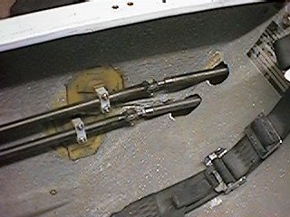
| Going back a little, here's the finished P-P tube guides mounted to the right cockpit sidewall. You can also see the junction between the forward and aft sections, where they meet with forks and rod ends. Later these P-P tubes will get covered by an aluminum cover. |
|
|
|
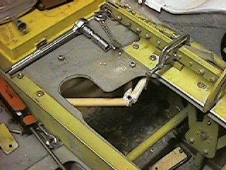
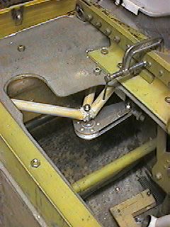
Here's the finished bellcrank in place on the tripod. I'm using the prototype tripod so that I can find the right length for the aft roll P-P tube. |
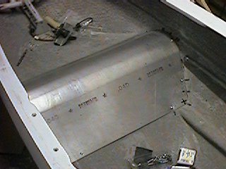
| And here I'm starting work on the aluminum access cover for the knee hump. The material is .040 6061-T6. It's pretty limber on its own, but when bent to shape and secured to what's left of the knee hump perimeter, it stiffens right up. There'll also be a couple of stiffening ribs where the instrument pedestal mounts. |
|
|
|
Here I've made the holes for the control stick and the P-P tubes. |
| And here I'm trying out pedestals. This is one that originally came with an HP-18 fuselage I bought from Bruce Patton. |
|
|
|
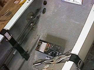
Here I'm starting to puzzle out what to do with the battery. You can also see the holes in the seat back where the P-P tubes go through. |
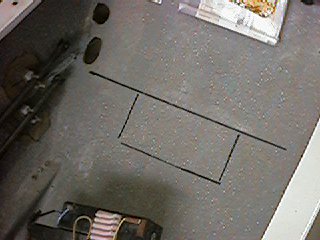
| The marks on the seat back bulkhead are where I cut it just forward of the landing gear well. There's just enough room down there for the battery and a little bit of padding. |
|
|
|
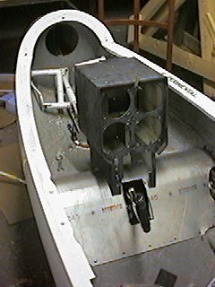
Here I've got the original instrument pod set in place on the two ribs I've riveted to the access cover. The instrument pod will be secured to the ribs with six #8 machine screws. |
page updated 04/09/01 all text and graphics copyright (c) 2001 HP Aircraft, LLC