After two tries to get the -701 platform fabbed on the wood jig, I gave up on it. Even with TIG welding, the welder could just barely tack weld the assembly without charring the jig. But with only those little tack welds, the assembly would pull out of alignment during the final welding.
What I ended up doing is having the welder make me a metal jig from my wooden prototype. That seems to work just fine, and now I've got the production jig for the 18-701 assembly just about done.
Now I'm working on finishing the jigs for the -702 pitch carriage assembly. That's not as touchy as the -701, since all the planes and axes are comfortably orthogonal. None of those weirdly sloped planes like where the -701 meets the mounting pads on the shell of the fuselage. Another weekend ought to see the completion of the -702 jigs.
Also, I'm starting work on the mockup for the -717 weldment. That assembly suspends the aft roll bellcrank below the rear spar carrythrough, about where the 18-439-16 pitch/roll decoupler goes in the stock control system. I've got a preliminary design that attaches using only the existing mounting holes for the main and rear spar carrythrough. Whether I use that design or go to one that uses one more hole depends on how rigid the assembly feels once it's mounted.
Here's the latest photos as of 22 September:
|
|
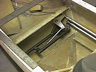
Here you're looking through the cutout in the knee hump at the prototype 18-701 and 18-702 assemblies. On the right side of the assembly is the roll bellcrank. You can also see the mockups of the longitudinal push-pull tubes. The lower one is for pitch, and the upper one is for roll. Notice that both of the push-pull tubes are on the right side of the cockpit, and that both are about as far from the plane of symmetry as I can get them. This preserves the lateral roominess of the cockpit. You can also see the transverse pushrod pointed towards the center of the cocpit where the stick will go. The -701 in this photo is one of the rejects from the wooden jig. It fits close enough for the purposes of demonstration, but isn't as good as one from the metal jig. The cutout in the knee hump is oversize for this prototype. Later, I'll go back and figure out how small I can make the cutout and still have enough access to install the system. |
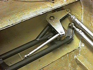
| Here you're looking at a closeup of what's going on at the right side of the assembly. The bellcrank horns on the pitch carriage assembly are clearly visible. Of course, what's missing are is the control stick, and also the parts on the pitch carriage assembly that support the stick and allow it to pivot for roll inputs. The -702 assembly in this photo is a fitment prototype that I glued together with 5-minute epoxy. |
|
page updated 04/02/01 all text and graphics copyright (c) 2001 HP Aircraft, LLC