This Update goes into a bit of detail about the leading edge joggle mold that I've been yammering about in the last couple of Updates.
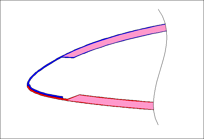
There are many ways of joining the upper and lower wing skins of composite wings. One relatively light and convenient method, the method I've chosen, is to mold a joggle flange into the upper skin and then bond it to the inner surface of the lower skin. In the following cross-section of the leading edge area, the upper skin material is shown in blue, the lower skin in red, and the sandwich foam in pink:

Now let's have a look at how we repeatably manufacture this convenient arrangement, and how we make the tools for it. We start by taking our wing plug, and dropping it back into the upper wing mold (both discussed in the previous Update):
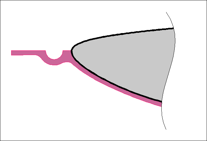
We wax up the flange area of the mold (including the squeeze-out trench) and the leading edge of the wing plug. Then we do one of those thick, messy tooling layups on the waxed area to produce the joggle tool. We made our joggle tool about 1/8" thick, using scraps of 7725, some Knytex DB170, and some 18 oz roving, and as usual a bunch of schmoo to get into the corners. For simplicity, this diagram shows the squeeze-out trench as hollow, but in reality we filled it right up with schmoo. The reason we molded the trench was because we use it as the locating feature to put the tool in the same spot every time.
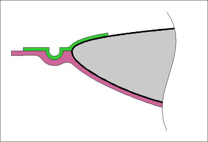
Next, we separate the joggle tool from the wing plug and mold, and then apply several layers of fiberglass cloth on the inner surface; the thickness of this layup is equal to the planned thickness of the lower wing skin plus about .010" for bonding epoxy.
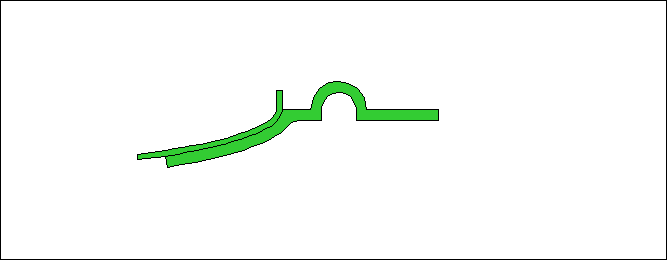
Then, of course, we trim the edges of the layup. That's pretty much how we make the joggle tool.
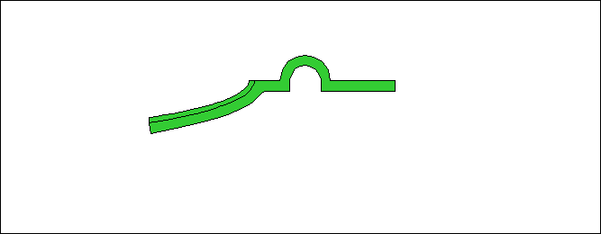
Now, here's how we use the joggle tool. We start by attaching it to the upper wing mold so that we can make the upper skin and its mating joggle. We use a line of 1/4" screws through the joggle tool and through the wing mold, with acorn nuts bonded onto the outside of the upper wing skin mold.
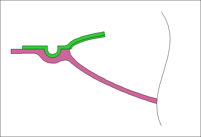
Then we do our layup of the upper wing skin.
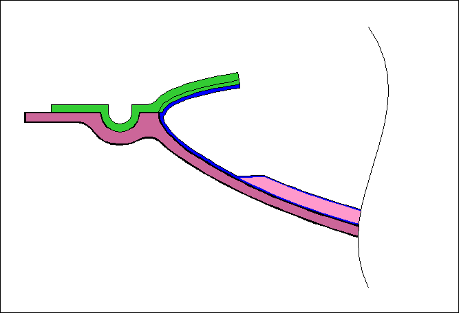
Once the wing skin has cured we remove the joggle tool to expose the joggle.
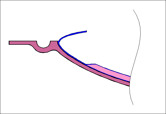
When we lay up the lower wing skin.
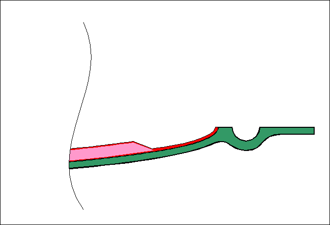
We arrange the upper and lower surfaces to ready them for bonding, and apply the bonding epoxy (in our case Epon 828 and Versamid 140, thickened with cotton flox).
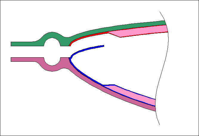
And then we bring the upper and lower molds together, and secure them together with a line of clamps along the flanges.
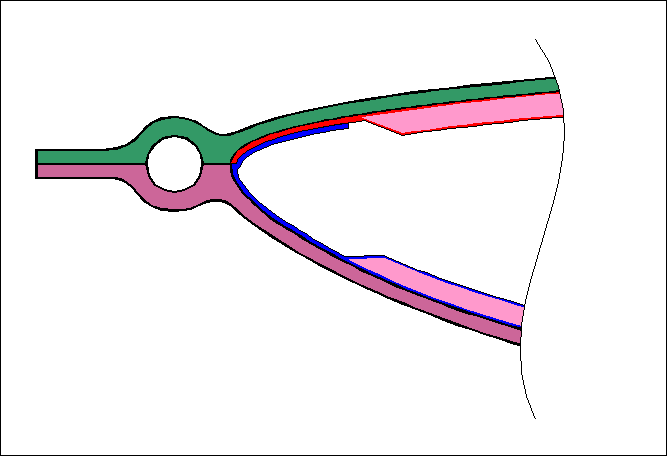
Once the bonding epoxy is cured, we remove the clamps and separate the bonded parts from the molds.
page updated 11 August 2006 all text and graphics copyright (c) 2006 HP Aircraft,
LLC