I took a one-weekend vacation from the wing tooling to get some work done on parts for the canopy jettison mechanism. This system attaches the canopy frame to the arm that pivots to open and close the canopy. What's required is a composite molding that transfers the bending moment applied by the weight of the canopy into the pivot arm. This molding bonds onto the forward end of the canopy frame (and may in future incarnations be part of the frame itself) and has features that index and attach it to the welded steel arm. Where the two come together there will be a quarter-turn release activated by a jettison knob available to the pilot.
Since my canopy is quite long, the bending moment at the attachment between the arm and the frame can be quite high. So the jettison platform molding has to be carefully designed to effectively transfer the bending moment without undue flexing or stress concentration.
At the pivot arm, I've decided to not use the rectangular welded steel shoe common on European ships of the DG and ASW pattern. Instead, I'm using T-shaped fixture made of welded steel tubing. The upright part of the T will be drilled for the shaft of the quarter-turn locking bar.
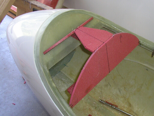
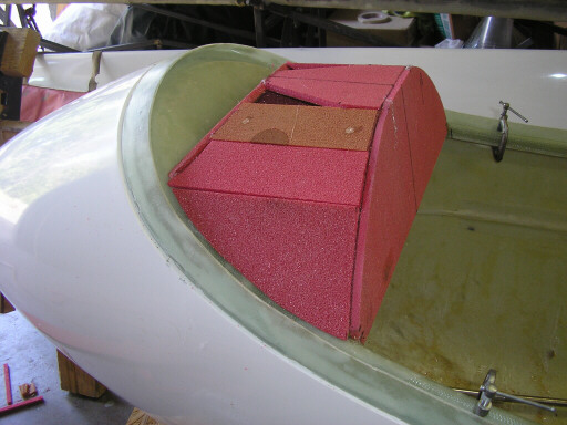
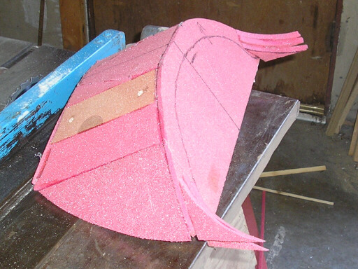
Here I've got the basic shape of the release platform scaffolded in with PVC foam. At this stage the aft face looks a bit like an instrument panel, but it is too small and too far forward for that.
The forward crescent is designed to allow the fitment of a crescent-shaped ventilation valve flap that pivots on a piano hinge.
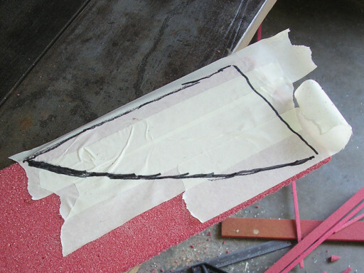
Here I've fleshed out the platform with a couple of planks of PVC. On this plank I'm using the old masking tape trick. You cover the target area with swaths of tape and draw the area outline on the tape...
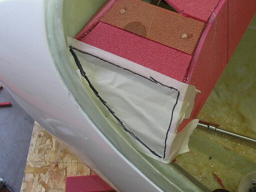
Then peel the tape off and stick it onto your planking material, which you trim to the outline...
And with some minor sanding and trimming it fits right in.
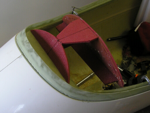
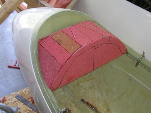
Here's the semi-finished jettison platform model. The arc drawn on the aft face is a future trim line, on the actual parts that face will be cut away along that line. The platform is quite faceted at this stage, but there's plenty of lattitude to sand it so its nice and round and swoopy like the instrument pod that Brad is developing. The only required elements are that it stays clear of the ventilation flap crescent and that the panel at top center stays flat and retains its double-trapezoid outline. This collection of foam will get sanded and smoothed and fiberglassed and smoothed some more, and later we'll make a mold off of it for the production parts.
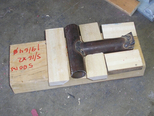
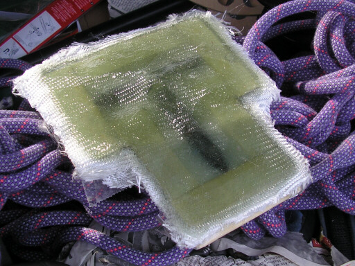
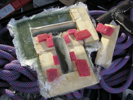
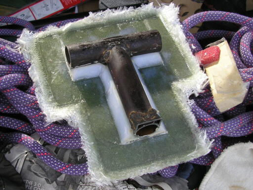
Here I'm starting work on tooling for the cradle that will interface with the T-bar at the end of the pivot arm. This cradle will get bonded to the underside of the jettison platform at top center. This is a rather awkward part to tool. Here I'm assembling a pre-plug from a welded steel T (which I made a long time ago) and some bits of doug fir. I fit all this junk together, glue it together with hot glue and PVC foam chocks...
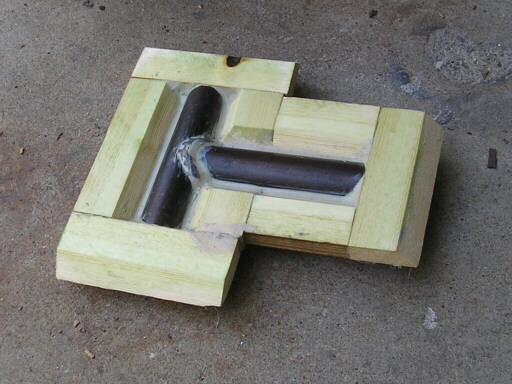
And when I flip it over it looks like this. Here I've filled off the bottoms of the trenches with modeling clay. Later, I applied some packing tape to the wood as a mold release, and filled in the trenches with epoxy and flox, and covered the whole thing with several layers of fiberglass. When it cures (it's actually probably cured now), it will serve as the plug for a mold that we'll make with a good tooling coat surface. That mold will be the tool we use to make the actual T-bar cradles.
Here's the jettison platform model lifted away from the canopy frame for finishing. Note the strakes that I added to increase the swoopiness of its look, and also reduce the stress concentration at the outboard edges of the aft face.
The T-bar cradle plug. In the background is my climbing rope (10.2mm Beal Edlinger II, great rope for a noob like me).
The back side, breaking the bits of the pre-plug away from the plug.
The liberated T-bar cradle plug. A bit of edge cleanup, a bit of modeling clay in the worst creases, and it's ready for molding.
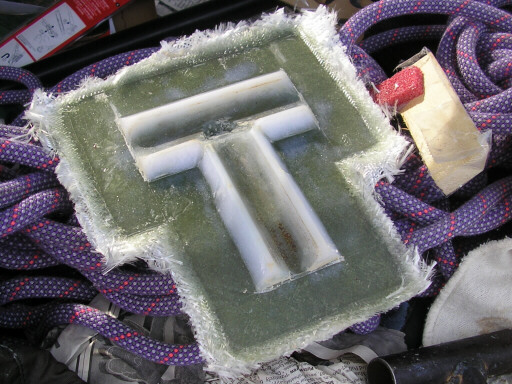
The fit between the T-bar cradle plug and the prototype T-bar is perfect.
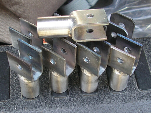
Here's the first batch of push-pull tube forks back from the welder. The builder grinds the corners off down to the scribed semi-circle, drills and reams the bolt holes to 1/4", primes them, and rivets them into the ends of the aluminum push-pull tubes.
Homebuilt aviation is not for folks who don't try things at home.
page updated 12 May 2008 all text and graphics copyright (c) 2008 HP Aircraft,
LLC