For a while now, I've been pondering how I was going to make the plugs for my control surface molds. Most of the surface is easy - I can either cut away the control surface of the wing or horizontal tail plug and use that, or I can use the molds I made from those plugs and make new plugs from the trailing edge portions of the molds. That's not the problem.
The problem is, how do I get nice, clean, smooth, radii to minimize the hinging gap between the control surface and the wing or horizontal stabilizer to which it is attached?
I've played around with a few schemes, and discovered that there are many ways of doing it. Unfortunately, most of them involve mass quantities of sandpaper, elbow grease, and good workmanship, all of which I hold in relatively limited supply.
The one way I have resolved to address this issue is with a router as shown in the following figure. Basically, I make a rough plug for the control surface and arrange it below the router bit so that the bit just touches the flattest part of the surface. Then I simply deflect the control surface around its hinge axis so that the router cuts away the proud portion of the overhang. Ta-da! Instant radius - for the width of the router bit, at least. All I need to do then is reset everything to translate the router by the bit diameter (less a little bit for some overlap) and then repeat.
As you can figure, that'd be fine for a couple of inches, but in the parlance of computer networking "isn't a very scaleable solution." And since I've got about 55 feet of this seal radius to form, there's great value in something that does scale well.
Enter the machine shown in cross-section below.
The carriage, shown in purple, rides on eight ball-bearings along two five-foot rails shown in green. Mounted on the carriage is a router, shown in red. Below the router, the control surface (blue) is mounted in an adjustable fixture such that the depth of cut is the same along the span of the surface, regardless of the taper of the surface. (Yes, this solution only works for linear tapers.)
The router will be translated down the rails using some sort of screw drive--probably just a 5-foot chunk of threaded rod that engages a nut welded to the carriage and turned by a crank at the end of the machine.
I figure that once I get the machine set up, I switch on the router and deflect the control surface through its travel to cut a 3/8" swath of radius. Then I turn the translation crank 5 turns to move the router 5/16" down the rails and deflect the surface again. It'll take 128 translations for the elevator, and about 460 translations for each flaperon section. I know that sounds like a lot, but I've done machine shop operations like that before, and once you get things set up right it goes pretty fast. And I think it's going to beat the heck out of sanding and filling and trying and adjusting the radius by eye.
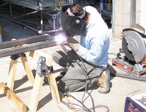
Anyhow, here are some photos of the radiator under construction. It took about a day to put together the rails and carriage, and the next step is to finish mounting the router and then build the hinge line support:
Welding the two rails together
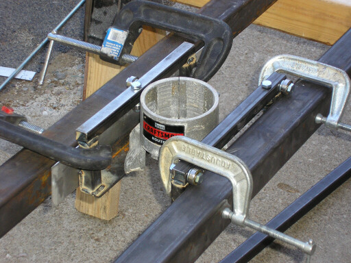
Trial-fitting the first carriage top member.
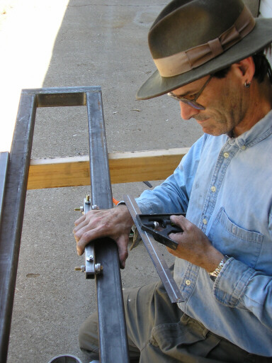
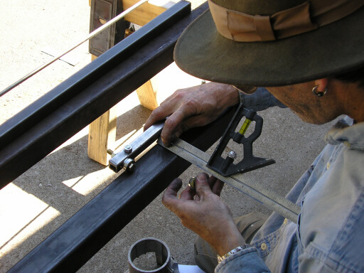
Measuring the carriage top member for the rest of the carriage parts
Carriage right and left chassis parts welded, getting ready to join them with crossmembers.
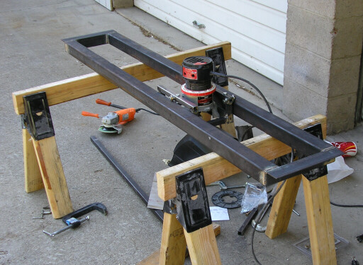
Basic carriage finished, test-fitting the router.
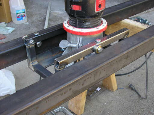
Closeup of router and carriage.
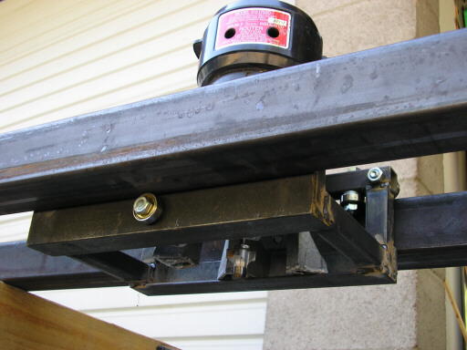
Looking up from below the carriage.
Next weekend I'm off to Yosemite to do the Royal Arches route again, with special attention to getting up and down the route in a single day. The weekend after, it's off to the gliderport to for sailplane rides for the kids.
page updated 12 September 2006 all text and graphics copyright (c) 2006 HP Aircraft,
LLC