This weekend I got to work in earnest on the new wing spar plugs for the HP-24. To recap earlier progress, several weeks ago I built a spar plug table. I used two 26-foot architectural joists for the sides and 26 feet of 16-inch wide by 3/4" thick fiberboard for the top. I added some 3/8" OSB to the bottom to close the box section tor good torsional rigidity.
What I got was a flat, straight, square platform for the spar plugs. I want good squareness and rigidity in this platform because I want nice, straight, wing spar parts with no excuses. I also want something that will survive the 300-mile trip to the composites shop where the spar plug will be used to make the spar molds.
When I'm done making the spar plugs, I'll transport the whole thing down to the composites shop for molding in my HP-18 trailer. After that, I'll retrieve the plug table, flip the 3/4-inch table top over, and use the same setup to start building the spar plugs for the two-seater.
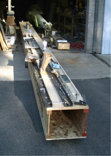
These photos show the steel channels and other guides that I'm using to make sure that the wing spars come out straight and with the specified spar depth at all stations.
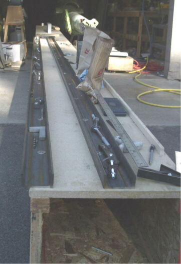
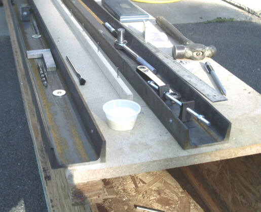
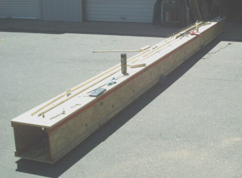
This photo shows my starting point for the 11 May session. You can see how my spar plug table is built from the end section. On the top surface, amid all the junk, are my two 14'4" long, 3" deep steel channels guides. If you look closely, you see that the guides are separated by pieces of allthread that set the gap between the guides. The allthread spacers are located on 28" centers.
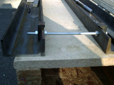
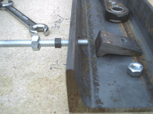
This photo shows a closeup of the end spacer. You can see the allthread, the nuts, and the angle spacer that I added to give the outboard nuts a flat seating surface. The angle spacers are necessary because steel channel has about a 6-degree angle on the inboard surface of the flange.
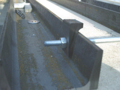
This photo shows a closeup of the angle spacer. You can see that it is just a chunk of flange from a section of steel channel.
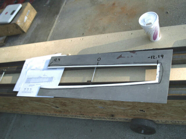
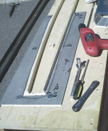
This photo shows my spar butt template, and the drawings I drew up earlier as a guide. I made the template by printing out the outline of the spar butt, gluing the printout to a piece of 1/8" 6061-T6, and bandsawing along the line. The hardest part was adjusting the template so that the gap at the open end conformed exactly to the side-of-body spar depth. I quickly discovered that I could easily adjust the gap the same way you straighten HP-14 spar caps - with a few well-placed blows from the flat face of a ball peen hammer.
This photo shows one of the secret ingredients to the guide spacers - the spacer bushing. That little bushing lets me drill the holes in the steel channel one size larger. And that extra clearance gives me the wiggle room that it takes to "un-parallel park" the threaded rods out of the guide channels once the channels are anchored to the table.
This photo shows the guide channels after they are anchored to the table, and after the spacer rods are removed.
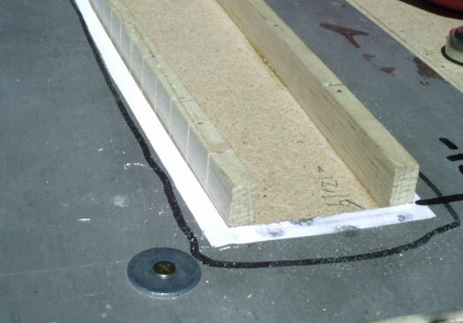
This photo shows where I'm getting ready to glue the plug strips in place onto the table top. You can see my custom-milled wooden strip, pre-drilled and with finishing nails pre-inserted. That wooden strip represents the trench in the mold where we'll lay in strips of carbon fiber. I've got several different sizes of wooden strip; each different size represents a different configuration of carbon strips. You can also see my little pot of glue and my acid brush. Brushing the glue on was actually not that useful; within a few minutes of starting I switched over to just squeezing a bead of glue onto the bottom of the wooden strip.
This photo shows the first strip nailed and glued in place.
This photo shows the transition between two different sizes of wooden strip.
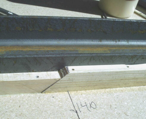
This photo shows the steel channels removed, and the spar butt template anchored in place on the tabletop. The template is aligned with the wooden strip that represents the top spar cap. The strip that represents the bottom spar cap is not yet anchored to the table.
This photo shows my secret for making the wooden strip flexible enough to conform to the curve on the template - I've bandsawed notches in it on 1-inch centers. The photo was taken just before I pressed the notched strip against the template edge and glued and nailed it in place. In the cleanup phase, I'll fill the notches with putty. And, yes, the notches will cause small discontinuities in the curve. However, the discontinuities will only cause deviations of about .005" from the intended arc, so they are of no consequence.
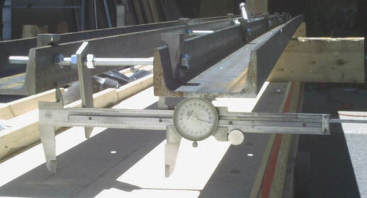
This photo shows how I've finished using the steel guides for the inboard spar section, and am re-calibrating it for the outboard section. I'm using my dial caliper to set the spacing to the nearest .001" at each of the seven spacing rods. In practical reality, the steel guide will deviate up to + .006 from the intended line, but that's still plenty, plenty close enough for this project. That bar of aluminum anchored to the spacing rod is part of the gunsight that I use to make sure that the outboard part of the spar lines up correctly with the inboard end.
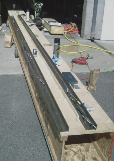
This photo shows where I stopped work on 11 May 2002. You can see the wooden strips representing the spar caps for the inboard section, and you can see the steel channels in place to guide the construction of the outboard section. You can also see the clutter and disarray that organizationally dysfucntional (read: messy) people like me tend to surround themselves with.
After I took that last photo, I wheeled the table back into the shop next to my HP-18, and took one of the kids in the neighborhood up for a ride on one of Amelia's Cessna 150s.
In the next session of work, I'll finish laying the last few feet of wooden strip for this spar plug, and then recalibrate the guide channels for a mirror image version.
page updated 13 May 2002 all text and graphics copyright (c) 2002 HP Aircraft, LLC