One of the better ways to get really nice TIG welded pieces is to just go out and get yourself a MIG welder. Use it to zap together a bunch of scrap steel into jigs for your parts. Then you cut your chromoly steel bits and load them into the jig. Then you take the whole mess down to the place where the TIG welding guy works, and have him weld together the actual parts. Works like a charm.
Brad wants to get to work fitting his control stick, so I temporarily suspended work on the wing tooling to get something done on the stick mechanism. The photos in this Update show a couple weekends worth of progress in that regard.
On 5 July, here's the jig and mockup for the pitch torque tube weldment. I did most of this the day before on 4 July, but I forgot to bring the camera that day, so no photos of the somewhat tedious process of making that jig.
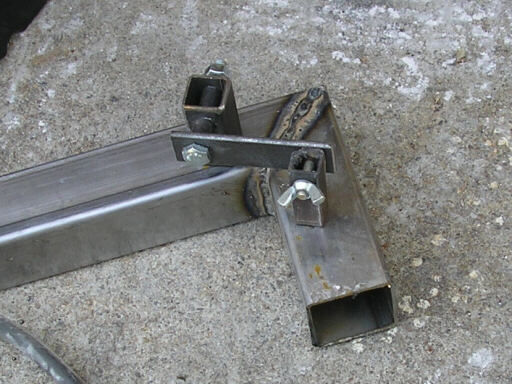
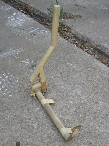
Here I'm starting the process of building the jig for the actual control stick. The large post embodies the fork where the stick attaches to the roll pivot bearings. The smaller post embodies the fork below the roll pivot where the control stick drives the lateral roll pushrod. The steel bar between them is a calibrated spacer that ensures that they are the right distance apart.
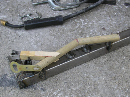
Two photos of the control stick mockup set onto the jig. It doesn't fit right down into the jig since the mockup is made with 13/16" dowel, and the jig is calibrated for 3/4" steel tubing. Note the green plate sheet part with the curved slot. That's the roll pivot stop, it engages a 5/16" tube on the pitch torque tube.
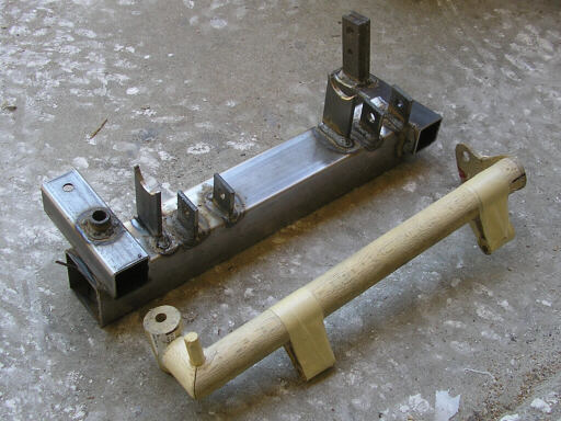
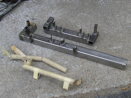
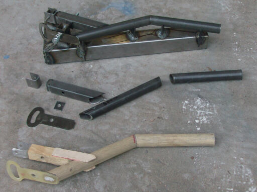
Here's my two completed jigs and my two mockups.
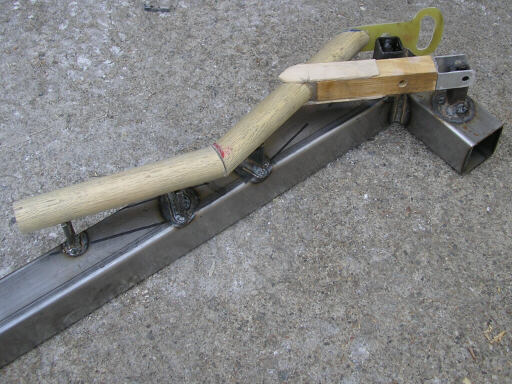
And, for reference, here's the two mockups assembled together. Note how the roll input stop plate engages the pin protruding forward from the pitch torque tube.
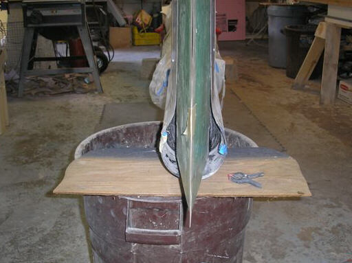
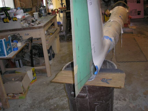
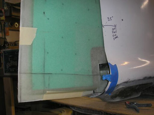
Forward to 10 July, here's some photos Brad took while test-fitting the first-article rudder. The rudder is green because its molded without gelcoat, and you can see right through the fiberglass to the core foam. It's made of fiberglass because it has to be radio-transparent; since the fuselage and fin are all carbon fiber, there's no place left except the rudder to put a radio antenna. Brad is going to assemble an RST-Engineering style copper foil dipole inside the rudder.
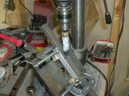
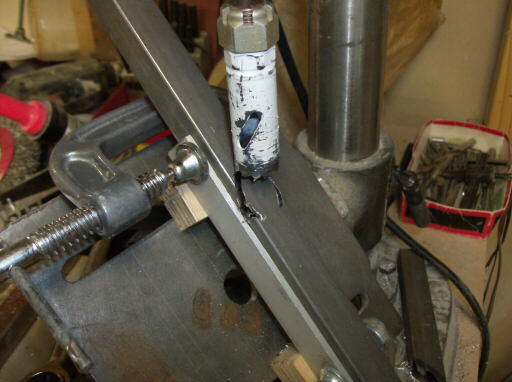
Forward to 13 July, and I'm cutting chromoly steel to load the control stick jigs. Here I'm making the awkward cut at the top of the square tube where it joins a round tube at a rather acute angle. I've got the drill press table tipped over at the correct angle, and I'm using a 3/4" holesaw on a pilotless arbor made from the threaded end of an AN8 bolt. This actually went pretty well, and I went ahead and made four pieces while I had the setup going.
A closeup of the loaded jig and the mockup, showing the CNC laser cut roll input stop plate that matches the green part on the mockup.
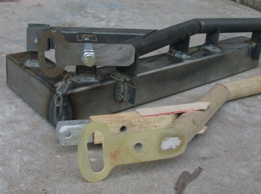
The loaded jig, the mockup, and between them cut chromoly parts for a second control stick assembly.
Homebuilt aviation is not for folks who don't try things at home.
page updated 14 July 2008 all text and graphics copyright (c) 2008 HP Aircraft,
LLC