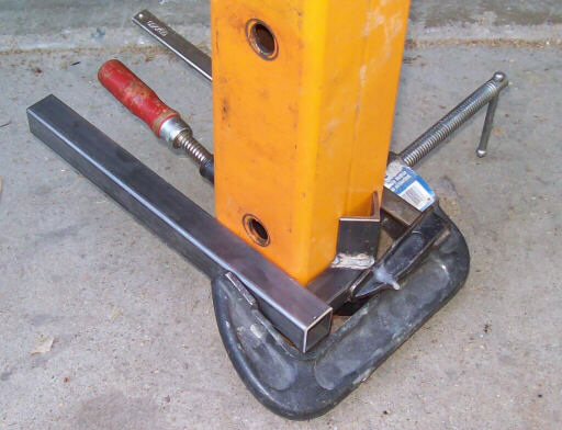
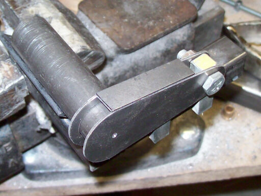
On 27 June, starting to weld up the airbrake arm jig. The orange square tube helps me hold the pivot tube cradle square to the jig foundation in two dimensions.
Welding in the locating lugs for the drive fork of the inboard two arms and the lower paddle pivot of all four arms.
The finished airbrake arm jig, ready for loading.
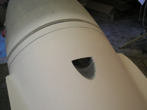
On 30 June, Brad's cockpit air exhaust vent, built into the turtledeck of his fuselage.
On 3 July, we took a day off and went to the ocean. Here's the girls at San Gregorio beach. It was about 100 degrees at the house, so it was nice to hang out in the more moderate temperatures at the beach.
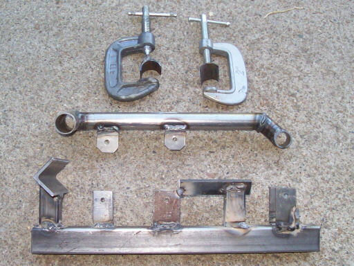
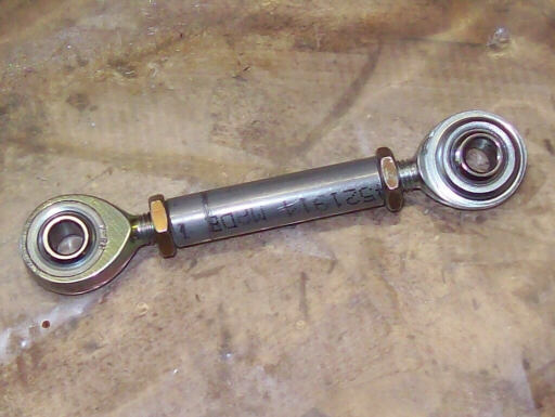
On 4 July, I've made a set of first article airbrake drive pushrods. They connect the inboard airbrake arm to the overcenter bellcrank. The rod end and locking nut on the left end haveleft-hand threaded to give the pushrod microstop adjustment for getting the airbrake cap compression just right.
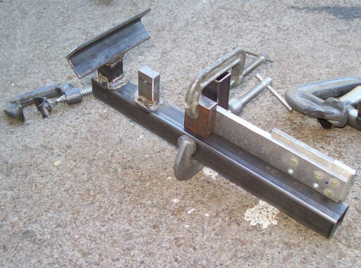
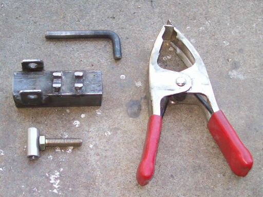
The jig for the length adjusters for the outboard airbrake arms. This feature also has microstop adjustment so you can make the airbrake cap compression identical at the inboard and outboard ends.
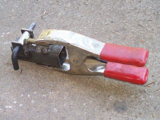
The jig, loaded.
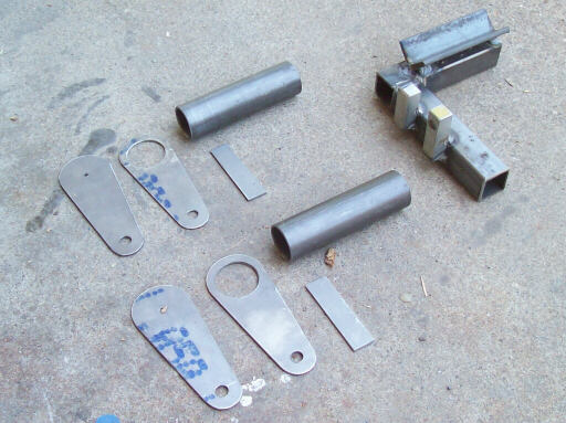
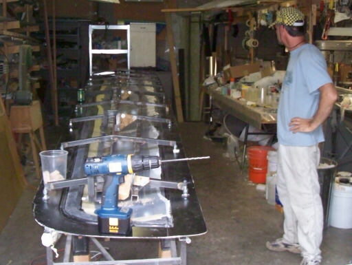
Back at the shop on 5 July, here's the loaded jig for the landing gear retraction driven crank.
The jig and parts cut for the first two cranks.
The driven crank is at the left edge of this overview drawing.
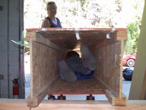
While putting away the narrow table, we ran the wheels into a sharp edge of the floor at the roll-up door (Rolladen HP), and both legs broke. We sent Raen into the inside of our Jeffries Tube to remove the nuts so we could replace the broken legs.
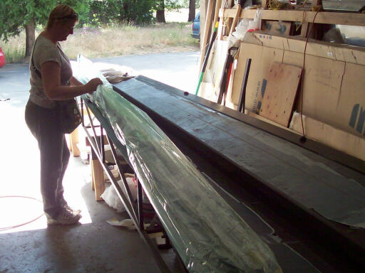
On 11 July, Brigitta unbags the left inboard drag spar that Doug and Brad had laid up the day before.
The upper right wing skin with polystyrene pylons and nails that we use to measure the internal clearance.
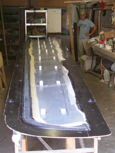
Lowering the lower right wing mold and skin onto the upper for the pylon test.
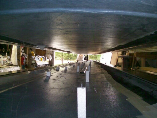
Removing the pylons and the hot glue residue.
It rained. In California in July; who'd have thought? Brigitta and the girls took refuge under our sunshade.
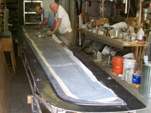
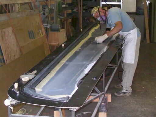
Here we've finished adding the spar locating clamps to the right wing spiders and are marking the skin for the spar trench.
Brad slits the inner skin with a moto tool. Yes, he is being very careful not to nick the outer skin. Some factories use a carefully calibrated plunge router for this, and we may do so in the future.
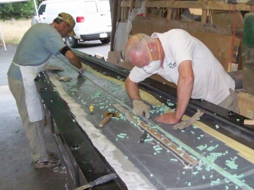
Brad and Doug remove the core foam from the trench. Yes, they are being very careful not to nick the outer skin.
Test fitting the spar in the trench. It fits well.
On 12 July, the trench is ready for spar installation.
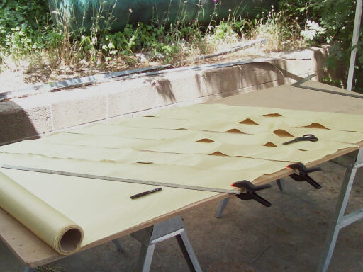
Cutting material for a set of outboard flaperon skins.
The flaperon skins, laid up and bagged. Under them, the spar is getting bonded into its trench in the upper right wing skin.
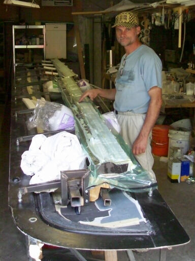
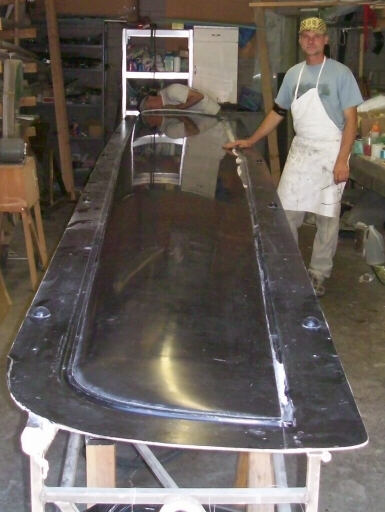
13 July. In order to locate the flaperon hinge gudgeons, we needed to trim the aft edges of the right lower wing skin. In order to do that, we had to pop the skin out of its mold. Here's the outer surface. A few pinholes, lots of black carbony goodness.
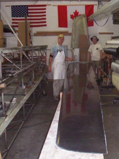
We carried the skin into the other shop and laid it on the upper right wing skin with the spar installed. Doug peeks into the root end to view the internal clearances. We weighed the skin, it came in at about 17 lbs.
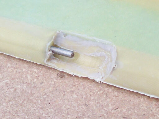
Here's one of the flaperon pintles before cleanup. It is quite a trick to mold these into place during the skin layup, with no extra process cycles required.
Homebuilt aviation is not for folks who don't try things at home.
page updated 14 July 2009 all text and graphics copyright (c) 2009 HP Aircraft,
LLC