Lately we've been cleaning up the right-side wing molds. We're pretty much done with that, and have got them about ready to go. The next thing on that front is to mark and scribe the mold surfaces for the flap/aileron separations and hinge lines. And then I'll make locators for the hinges and spars and stuff.
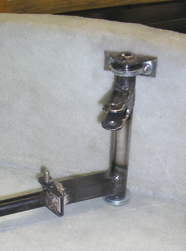
One interesting thing I've allowed myself to start work on is the landing gear idler and uplock arm. This little wiggly bit goes inside the right side gear well box just behind the pilot's right elbow. It has two purposes: it embodies the uplock that keeps the gear retracted at 1g+ conditions, and it translates the motion of the gear retraction system inboard from sta.R.9.5" where the gear handle is to sta.R.5.3" where the drive arm is.
This little bit is what most differentiates the landing gear retraction mechanism of the HP-24 from that of the HP-18. While the HP-18 system is the very soul of simplicity, it also leaves something to be desired in terms of smoothness, ergonomics, and uplock power. It's pretty common for legacy HP ships to let the gear poke out of the gear doors in 1g+ flight, such as perhaps a 60-degree bank in a tight thermal. Also, in the HP-18 the gear handle goes forward for down-and-locked, which somehwhat violates the model of pushing controls forward when you want to go fast, and pulling them back when you want to slow down and land.
In the landing gear system I have sketched out, the pilot has a pivoting handle on the right side armrest rail. The lever pivots through about 90 degrees. In the up-and-locked position, the lever stands straight up, placing its round black knob well within the pilot's peripheral vision. In the down-and-locked position, the lever points straight back, and is slightly recessed into a trench in the armrest rail. The lever is locally locked into the up and down positions by a pin on the outboard face of the lever that engages holes in the side of the cockpit wall. The pilot unlocks the lever by pulling it inboard to move it between the up and down positions.
The control lever drives a longitudinal push-pull tube that drives the idler and uplock arm. The idler and uplock arm drives another push-pull tube that drives the landing gear at its aft pivot. The pivot that joins the idler and the final drive PP tube incorporates an over-center uplock that is geometrically similar to the main downlock incorporated in the landing gear legs.
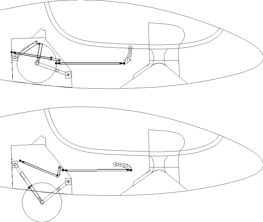
Here's a quickie sketch of the overall gear retraction system, showing both the retracted and extended positions. Note that the gear yoke and legs are basically the same as on the HP-18. Also note that in the up-and-locked position the drive PP tube protrudes through the aft wall of the landing gear box. The HP-18 system also does this, though to a greater degree:
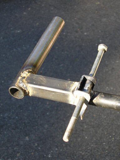
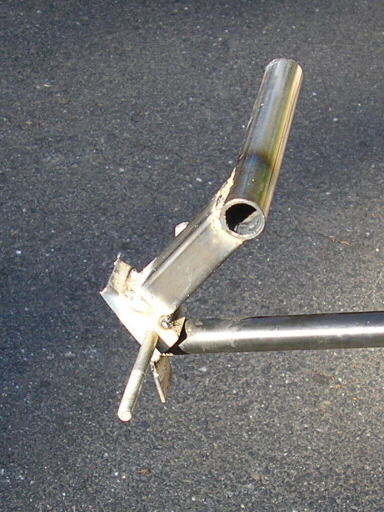
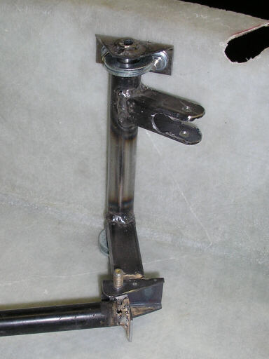
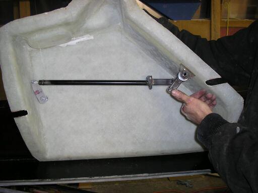
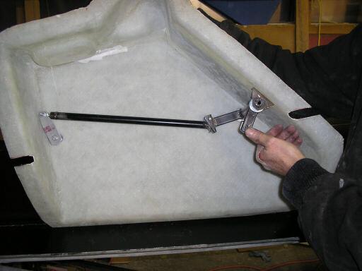
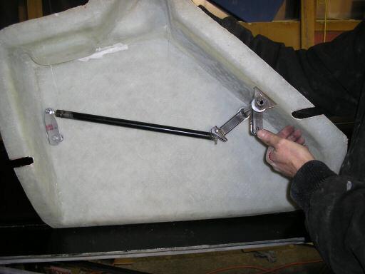
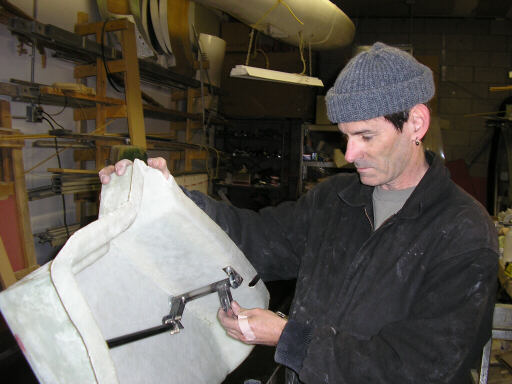
And here's some photos of the mockup prototypes under development. All the metal bits in these pictures are slapped together out of whatever mild steel came to hand and zapped together with my MIG torch. They're not flight articles, they're only to size up the system and make production jigs from:
These two photos show the overcenter part of the idler, before welding the outboard arm on. The long bolt is just whatever was handy at the time.
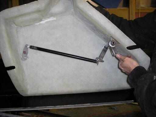
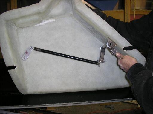
These two photos show the idler mounted on its axle and brackets and installed in the right-side gear well box. The first shows the down position, the second shows the up-and-locked overcenter position.
These five photos show the gear extension cycle for the stuff inside the right-side gear well box.
This photo is a still frame from a video we took of me introducing the system. My intent was to post it on Youtube.com, but after reviewing it I decided we ought to re-do it. No wonder the MythBusters guys passed me over...
Next weekend I'll be in Monroe, Washington helping Brad develop tooling for internals on the Glidair. We'll be focusing just on the stuff that it takes to close the fuselage shells; stuff like elevator circuit guide supports, templates for locating rudder cables, and things like that.
page updated 15 January 2007 all text and graphics copyright (c) 2007 HP Aircraft,
LLC