We convened a very successful Akaflieg Douglas Flat 6 March through 15 March 2010. Brad came down from Monroe (near Seattle), and Doug came over from Reno. We assembled and installed the airbrake and flaperon control systems for both of Brad's wings, and then we closed the wings. Brad and Doug also closed Brad's four flaperon sections.
Doug and Brad spent most of 6 through 8 March making the last few composite parts we hadn't gotten to, including the remaining root ribs, the airbrake box ends, and a pair of half-ribs to anchor the pivot at the outboard end of the flaperon balance mass.
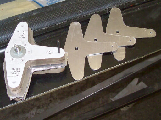
On 7 March, I made the leaves for the T-shaped inboard flaperon bellcrank. Needing four identical leaves, I made a pair of particle board templates, a stack of aluminum rough blanks, and then milled the blanks to the template outline using a router with a carbide bit. The HummelBird builders swear by that technique for making wing rib blanks, and I can see why. Chalk one up for See'n'saw.
On 8 March, Brad prepares to make the mounting pads for the four lift pins on the root ribs.
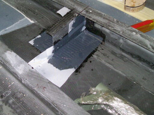
On 9 March, I've painted and assembled the inboard flaperon drive bellcranks, and Brad has located and potted their mounting pads. The hill of shmoo under this bellcrank will get some sanding and a few ply of carbon before we call it done.
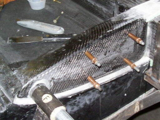
Later that day, Brad at work bonding the gudgeons onto the aft edge of the lower right wing skin. Brad wanted to get this step done before closing the wing made the access much tighter.
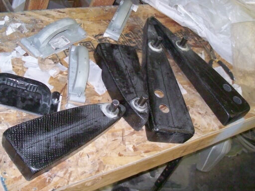
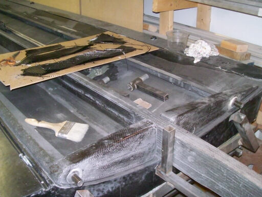
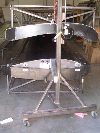
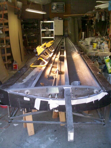
The left wing airbrake box and the airbrake arms and overcenter crank, all assembled and ready.
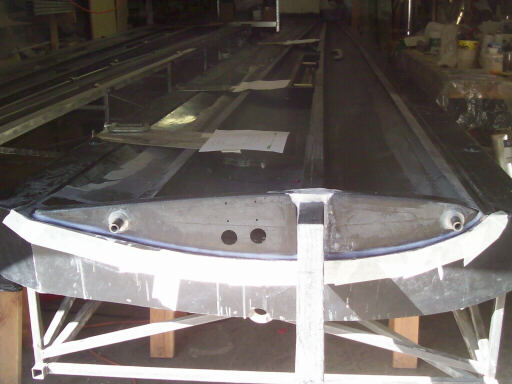
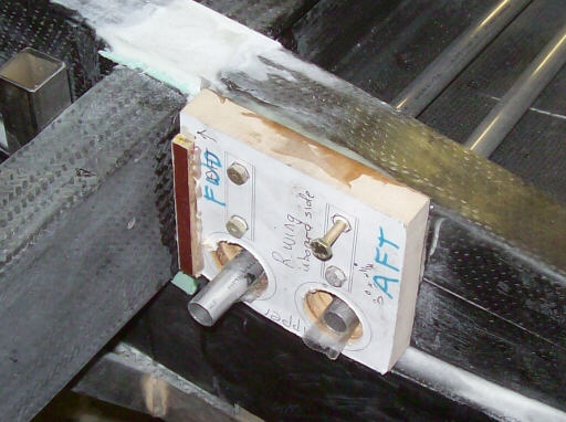
On 10 March, the four root ribs with the lift pins mounted. Note that we've also drilled the two holes for push-pull tube access on each root rib, and also the four holes each for the auto-connect bellcrank mounting brackets.
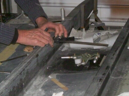
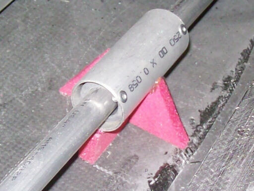
Doug centers the right wing inboard flaperon bellcrank so that we can measure the distance between it and the outboard bellcrank and so make the push-pull tube the right length. The distance is greater than 8 feet, so we had to rivet sections of tube together using splice plugs left over from HP-11 kit production. We also used the same double-dimple technique as on the HP-11 to get flush heads on both the manufactured and shop heads of the rivet so that the tube could be slid out of the guides for repair.
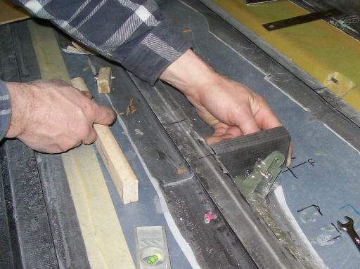
Brad trims and fits the half-rib that anchors the outboard end of the flaperon balance mass.
The half-rib, taped into place and peel-plyed.
The right root ribs, located with the lift pin alignment fixture and being bonded into place.
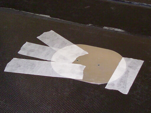
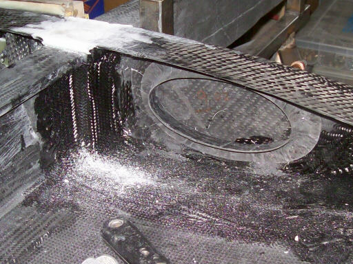
On 11 March, we're locating the inspection openings that allow access to mechanical parts through the lower skin.
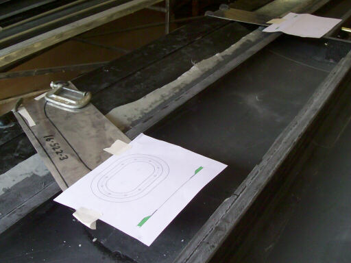
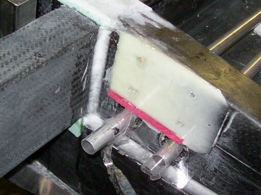
You can see that we have paper templates suspended over the mechanicals by scraps of aluminum clamped to the aft mold flange.
And here we've slid the lower skin into place under the opening templates. After this, we tape the templates to the lower skin, remove the aluminum scraps, and then drill through the lower skin at the two foci of each access oval.
Brad prepares to bond in the left wing root ribs.
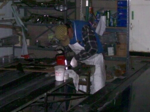
Here Brad is bonding in the left root ribs. It doesn't show up well in this photo, but the power has gone out, and Brad is working by the light of a fluorescent camping lantern. A few minutes after this photo we rigged a propane radiant heater to keep things warm.
Here we have the right upper wing skin cleaned off and ready go into the storage room so that we can concentrate on closing the left wing.
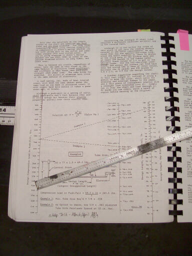
Using Stan Hall's 1989 article on simplified push-pull tube design to decide how many guides I need on the airbrake push-pull tube. Based on this and my estimate of the overcenter load, I think I can get away with only one guide.
Marking the access opening on the left wing bottom skin. Now I have made a set of three aluminum templates that show where the inner skin is cut, where the foam is beveled to on the outer skin, and the outline of the actual opening to be cut later.
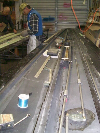
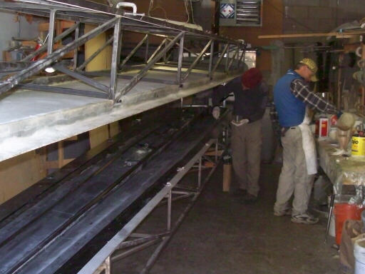
Brad and Doug work on flaperons while I locate the guides for the left wing push-pull tubes.
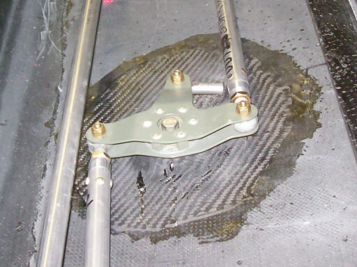
A closeup of the left inboard flaperon drive bellcrank, all installed and ready. The slot through the upper skin for the actual flaperon pushrod is not yet cut; Brad will do that when he installs the drive horns on the flaperons.
On 12 March, the left wing flaperons closed. The end ribs will just be pours of epoxy and microballoons,
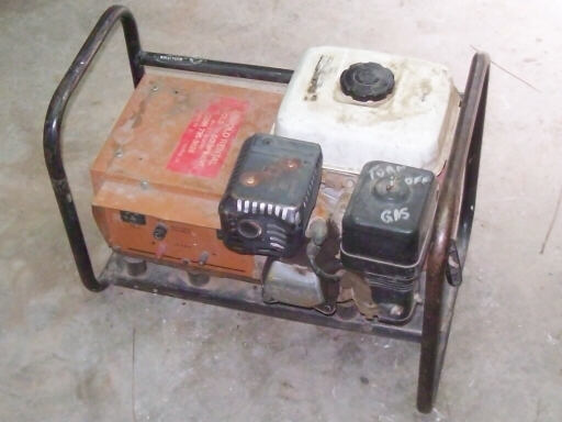
The weather was looking iffy, and we'd already had several power outages, so we decided to invest in some storm insurance and rent a generator in case the power went out while we were bonding a wing togehter. It worked great; as soon as we had the generator in hand the weather improved and the power stayed on without interruption.
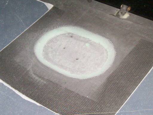
A typical inspection opening prior to the application of the reinforcing plies that close out the foam sandwich.
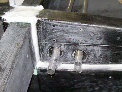
The left wing root rib, showing the push-pull tube exits and the mounting holes for the auto-connect bellcrank brackets.
Doug applies the wedge-shaped pour of flox that makes the bellcrank mounting surface parallel with the fuselage plane of symmetry. The root rib webs are toed-out by about 3 degrees, but the bellcranks have to be normal to the plane of symmetry.
Brad closes out one of the inspection openings. This is the one for acess to the left outboard flaperon drive bellcrank; you can tell by the nearby depression for the bellcrank lower pivot mount.
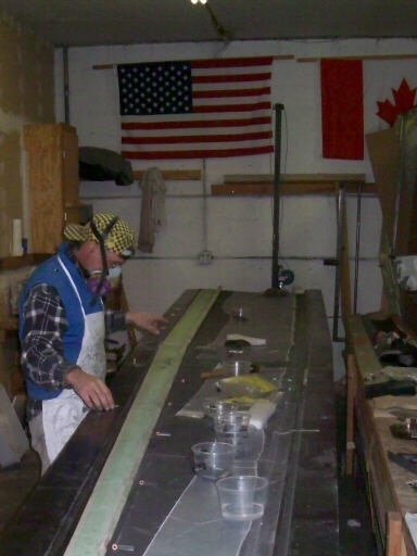
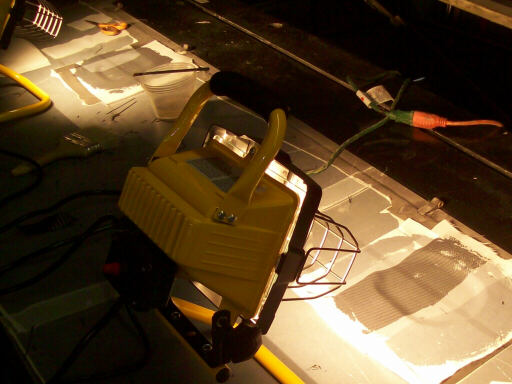
Curing the access opening closeouts using 1KW lamps in the storage room.
Brad clecos in the elliptical reinforcing ring that stiffens the forward root rib around the future location of the ballast bag cutout.
The reinforcing ring on the inside surface of the rib.
Here's that pour of flox that levels the web of the root rib where the autoconnect bellcrank brackets go.
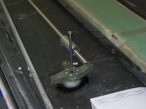
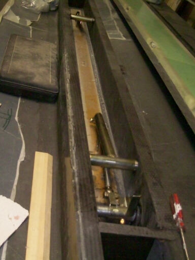
I agonized for days about how to locate and secure this airbrake push-pull tube guide. But in the end, we just located it in space, put a couple of PVC foam blocks under it, and "omega taped" over the guide and blocks with fiberglass.
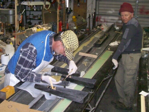
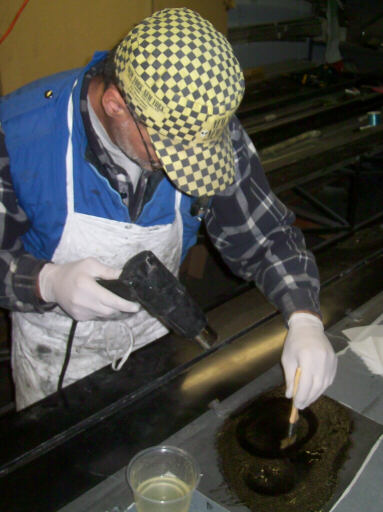
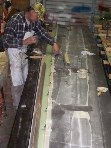
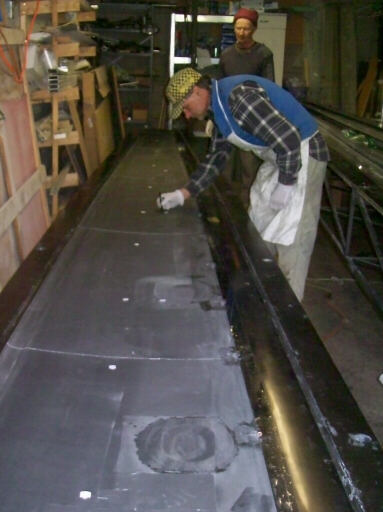
Showtime! On 13 March, Doug wets out the bonding surfaces on the left wing upper skin while Brad mixes the bonding paste that will stick it to the lower skin.
The bonding done, we clamp the two molds together with 2x4s on 13 spanwise stations, 26 one-foot chunks of 3/8" allthread, and 52 nuts and washers.
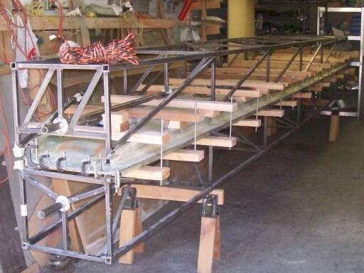
No whist for the wretched! Immediately the closure made, we roll in the right lower mold and skin so Brad can get to work on its flaperons and pivot gudgeons.
Brad and Doug close the right flaperons using clecos and weights.
Brad releases the inboard right flaperon and pivots it.
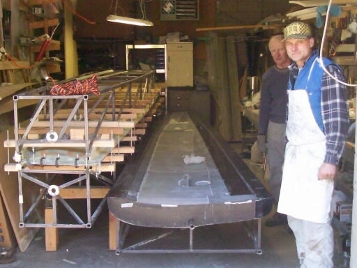
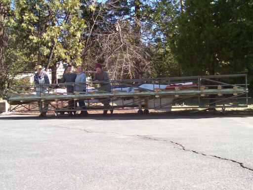
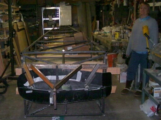
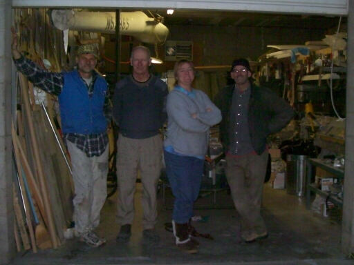
On 14 March, we encountered this group photo op while swapping the closed mold into the storage room and the upper right mold and skin into the working bay.
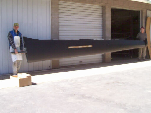
The lower skin was already free of its mold, and it only took a bit of work around the root rib to free the upper skin so I could raise the mold off of it.
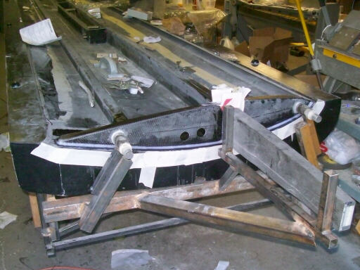
Brad and Doug hold the wing while we take care of the first order of business: weighing the wing. Without finish, flaperons, or airbrake caps and blades, but with the flaperon balance mass, it came in at 80.5 lbs. Brigitta won the weight pool with a guess of 81 lbs, and Raen and Brad came close with 83 and 85 lbs respectively.
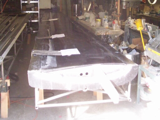
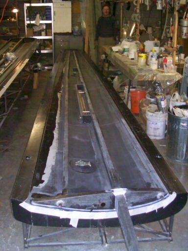
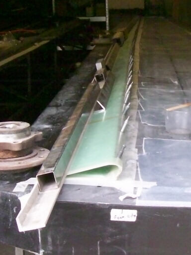
Still ragged along the upper aft edge, we show off the classic double-taper planform.
Back at it! Here we accelerate the cure of the push-pull tube guide omega tapes in the right wing so that we can close it that day.
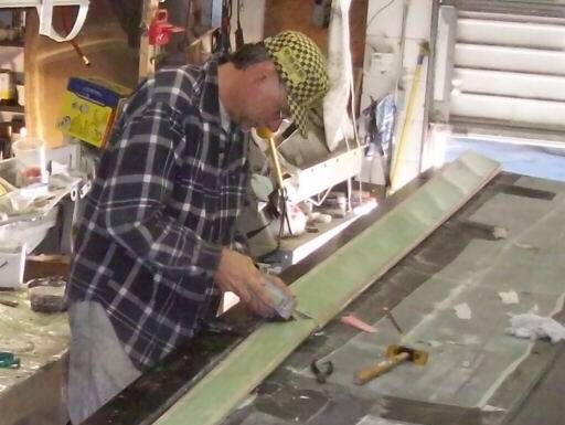
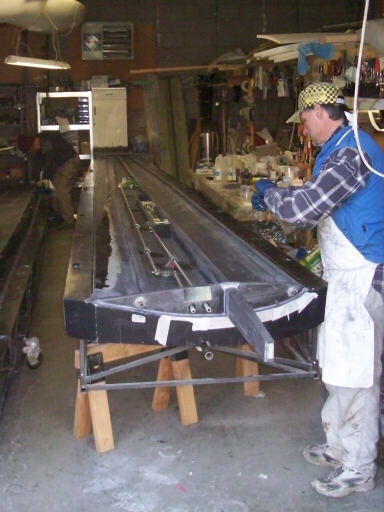
Marking the lower right wing skin with the bondline locations so that we can prime them with neat resin. The white patches are pieces of paper that we transferred from the spar and half-ribs using rolled bits of masking tape.
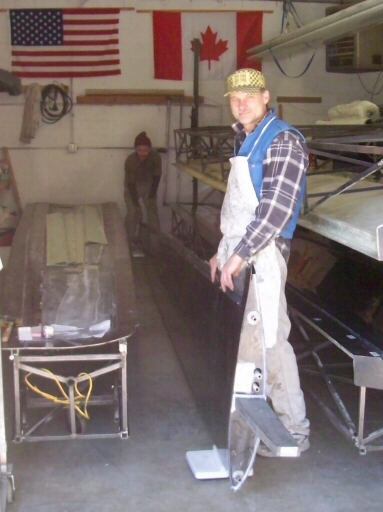
Brad gloves-up for the closure.
Two hours later, it's closed, rolled, and clamped. You can see that we've put the lift pin fixture back on after the close so that the lift pins stay in alignment as the root rib bonds cure.
The usual Akaflieg Douglas Flat suspects: Brad Hill, Doug Gray, Brigitta Kuykendall, and Bob Kuykendall. On 15 March, I went back to work while Doug and Brad cleaned up the left wing aft edges and tidied up the shop a bit.
Homebuilt aviation is not for folks who don't try things at home.
page updated 16 March 2010 all text and graphics copyright (c) 2010 HP Aircraft,
LLC