We had Brad Hill and Doug Gray working in the shop on 23 through 28 April, with Brigitta and I there on 23 through 26 April.
Our primary objective was to do the dihedral alignment between the wing plugs and the fuselage plug. The purpose of this operation was to glue the outboard ends of the wing fillets onto the wing plugs in the proper position and orientation so that they matched perfectly with the portion of the wing fillet that is embodied in the fuselage molds.
Secondary objectives for the week were to get the wing plugs packed into a trailer for their trip to Brad's shop for final finishing, to make molds for the revised wheel well boxes, and to join the right and left skins of the fin spar plug. We got all that stuff done, and more.
Getting back to the wing fillets, if you'll recall back when Harald made the wing fillet on the fuselage plug, he made it 25" wide. Later, he separated the outboard portions of the fillets and saved them for me. The operation we just undertook is what we were saving them for.
When Harald made the fillets, he included two steel tubes whose locations corresponded with the expected locations of the transverse lift carrythrough tubes in the actual fuselage. When he cut away the outboard portions of the fillets, stub portions of these tube were included. The first part of the operation was to make stub pins that fit inside the steel tubes to join the inboard and outboard portions of the fillets.
I made the joining pins with angle brackets that we could use with adjustment bolts to correctly set the wing incidence to the fillet so that the two wings matched exactly. To assist in that part of the operation, I made two identical templates of the wing root profile.
Anyhow, the basic operation was to set the fuselage plug up with the wing fillets, add the wing plugs to the sides of the fuselage, position everything just right, and then temporarily glue the outboard fillets to the wing plugs.
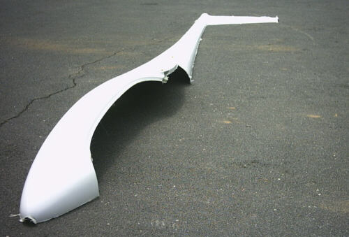
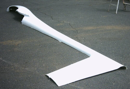
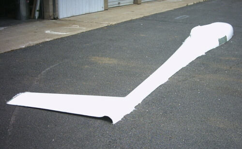
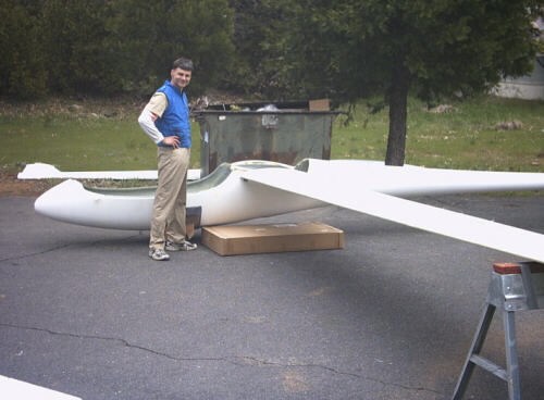
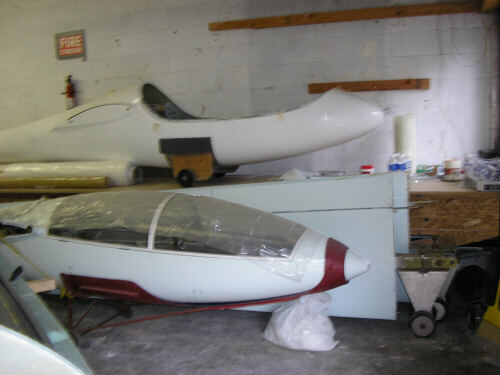
Also, as part of the operation of getting the wing plugs out of the rafters we also had to set the first fuselage shell aside out of the shop. We took a couple of photos of it and weighed it while we had the chance. Here's three photos of the first right-side fuselage shell. I'm depating whether or not to use it, since the next shell set will have a very much revised layup schedule.
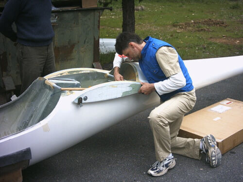
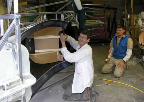
Here's Brad securing the left side wing fillet onto the fuselage plug. We just used threaded rod and big washers to hold the fillets on. Also note the angle bracket and adjustment bolt at the forward end of the fillet.
Here's Brad standing proudly after we have positioned the left wing plug.
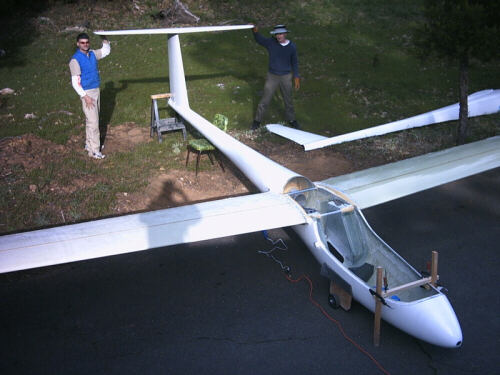
Here Doug and Brad hold the horizontal tail plug in position; both wing plugss are already in place and the fillets are temporarily glued on. The alignments for this operation were determined by a combination of digital leveling, linear measurements, sight strings, and a plumb bob. The fuselage is leveled side-to-side using a plumb bob on the vertical fin. The wing dihedral is set with a digital level (good to about +/- .1 degree) set on the wing surface, and the fuselage longitudinal angle is set with the digital level on the conical portion of the aft fuselage. The relative incidence between the two wing plugs is set by sighting across two identical templates set on the wing roots.
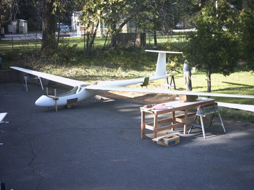
Another picture of the same operation. The pieces on the cardboard box are the wing root templates, and the pink shapes on the workbench are the cores for the default wingtip plugs. When we measured the wingspan without the default tips, it came out exactly as expected. However, the default wing tips came out a bit longer than expected - adding up to about 15042.7 mm. We'll have to go back and shave about 21.3 mm off of each of the default tips before bonding them to the wing plugs.
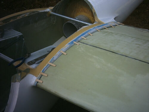
Here you can see how we temporarily glued the wing fillets onto the wing plugs. The things that look like pieces of popsicle sticks are just that. They bridge between the wing plug and fillet and are bonded on with hot melt glue.
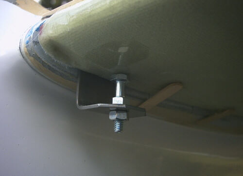
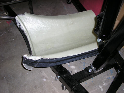
This shot shows the adjustment provisions I added to each of the four stub pins that aligned the fillets to the fuselage. I just adjusted the height of the bolt head until the wing plug looked right against the fillet and so that the incidence angles of the two wing plugs matched exactly.
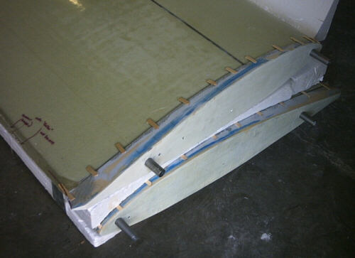
Here are the two wing plugs removed and set aside. You can see the stub pins that joined the fillet to the fuselage. These pins will give us the basis for locating the actual lift pins in the wing molds.
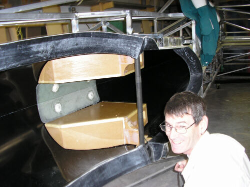
Brad looks on as I work on the wheel well box plugs. I've used an alignment fixture secured to the two boxes and to a steel tube between the locating holes for the forward lift carrythrough to align the boxes. The boxes have already been glued into the mold with hot melt, and now I'm removing the alignment fixtures.
Here the alignment fixture and tube are out, and the boxes are securely in their positions. I'm a happy camper!
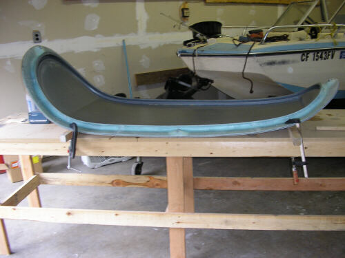
Fast forward a few days, this is a turtledeck that Brad made to test various layup techniques.
And here's the canopy frame mold readied for another test article.
My collection of HP junk at the shop.
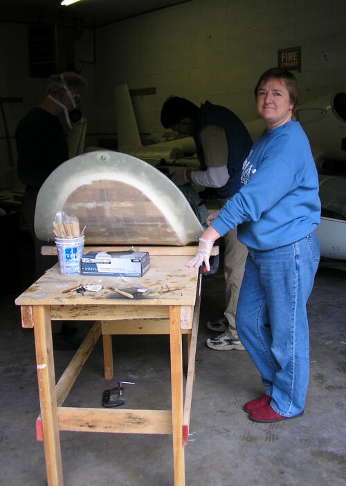
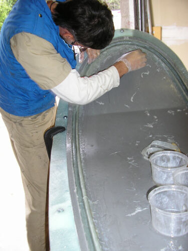
Brigitta and Brad at work on a canopy frame.
Brad and Doug at work on the canopy frame.
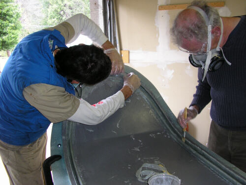
Brad still at work on the canopy frame...
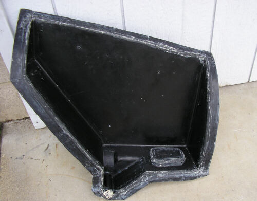
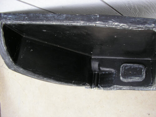
Two pictures of the wheel well box molds. The do need some cleanup and some minor filling, but I think I'll get good parts out of them.
More pictures to come; Brad's going to burn me a CD full from his own digital camera and send them down in snailmail...
page updated 1 May 2005 all text and graphics copyright (c) 2005 HP Aircraft, LLC