Last weekend I finished welding up a couple of sets of the landing gear oleo part. This weekend I was back at work on some core parts of the HP-24 project - the airbrakes. I need to finalize the airbrake design (at least a firtst-article version of it) before we can tool up and make the first wings.
I've been dreading the airbrake development. For one thing, there's almost no precedent in Dick Screder's design legacy for airbrakes, and for another there are many hidden subtleties that wait in the wings you bite you later. Especially when it comes to relatively shallow, relatively limber wings like mine.
Well, anyhow, I've pretty much given up on developing huge mondo-powerful airbrakes, and decided to be satisfied if I manage to make something that's simple and relatively effective. Later I can go back and apply the lessons of the first article to try to make them more effective if necessary.
What I'm going to do is build a mockup airbrake installation using these arms and a box made of fiberboard and masonite. That will give me a quick-and-dirty testbed for refining the airbrake system and developing something that works and is buildable and installable. I figure that the hardest part will be developing the geometry of the arms and retraction overcenter (yes, another darn overcenter!) that holds the paddles retracted against the springs that secure the airbrake cap strips.
At the end of this weekend's work, I suddenly realized that I also had a bunch of bicycle fixing to do back at home, but no bicycle stand. I used to do work like that by just inverting the bike onto seat and handlebars, but with today's bicycles that just doesn't work so well anymore. Especially since a lot of what I have to do requires twiddling of the front and rear derailer controls to make the indicators coincide with the selected gears.
So with about fifteen minutes left to the workday I used the MIG welder to zotch together a bike workstand. It turned out OK, and on Monday I used it while building up a mountain bike for Alia.
Also, in case you missed it, Brad Hill has been plugging away at the Glidair internals, and now has tooling for most of the aft fuselage and vertical fin ribs and bulkheads, and also the fin spar. See the Glidair page at:
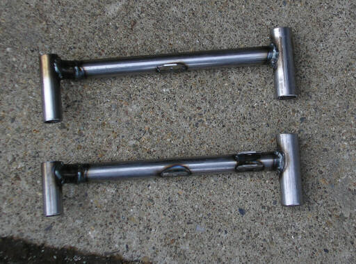
In-plane view of the two airbrake arms. The welding is pretty nasty, but that's OK since these are not flight articles. The ends on the right are the upper ends that will engage bushings bolted to the primary paddles. The ends on the left are the lower ends; they pivot on bushings that engage longitudinal shafts that go through both walls of the airbrake box. In this photo the upper ends are in as-welded length; later I shortened them to fit into the J-section primary paddle.
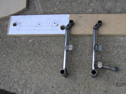
Axial view of the two airbrake arms, including the rudimentary welding jig I aligned them with. The development mockup that these are for represents the port wing installation; here you're looking at the aft faces of the arms. The one on the right, with the drive dogbone attached, is the inboard arm. Both arms have the intermediate paddle pivot tang about halfway up. The little kink near the upper end of the arm helps get the upper pivot as high inside the wing as I can while still keeping the arm free of the cap strip spring studs. Maximizing the height difference between the upper and lower pivots is key to having a simple airbrake system that doesn't require a drive rod between the inboard and outboard arms. On 15% thick wings, things like this aren't so important. But down around 13.5% they do start getting troublesome.
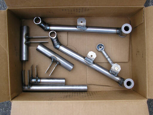
The weekend's haul. This box contains the two arm prototypes (shown with bottom end bushings pressed into place), and also two each of the airbrake idler/overcenter bellcrank parts. I've got something interesting planned for the airbrake drive, and if it works out it will let me eliminate the rubber bellows that everyone else uses to seal the airbrake box off from the rest of the wing - the bellows that rots out after 20 years and which you can only replace by cutting a hole in the bottom of the wing.
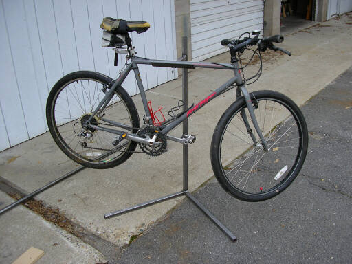
In the foreground is the bicycle stand I welded up in the last fifteen minutes of shop time. The material is about 10 feet of 1" square mild steel tubing and about 8" of 2"x2"x1/8" angle iron. I jigged it out by eye, using nothing more substantial for alignment than TLAR (That Looks About Right) and a pair of those red arrowhead welding magnets.
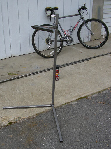
It works! Here it is supporting my beater bike.
page updated 20 February 2007 all text and graphics copyright (c) 2007 HP Aircraft,
LLC