We're still working on it!
The plug for the fiberglass forward fuselage is now about done. A little more sanding, and a coat of paint, and we'll set it aside until it's time to pull molds off of it.
I've got the wing spar design locked down, and I've signed a contract for the tooling for the spars. The spar is now sized for 18-meter tips. That adds a handful of carbon, but not so much as you'd notice. The biggest difference is in the stiffness - I think that it'll ride a bit harsh in 15m configuration, especially with light weight pilots. Not as harsh as a metal ship, but noticeably more so than an ASW-20 or such. The tooling should be done in about 10 weeks. We probably won't have a finished wing spar set until after the convention, but it'd be neat if I had a set to show off there.
I've updated the HP-24 3-view drawing to have an all-curved canopy line like the ASW-24/27 and the LS-10. We're well short of starting the molds that will embody the cockpit rail details, so this will be a fairly easy change at this time. I might even make the rail lower at it's nadir; I've still got plenty of freedom in that regard.
I've also updated the 3-view drawing to show the 18 meter tips and the new cockpit rail design. The specs also show a weight increase based on the new spar and diminishing optimism about how light I can make the non-lifting parts. The latest 3-view drawing is at:
http://www.hpaircraft.com/hp-24/web_24T_3view.pdf
The next design task will be to do the lofting for the plug for the T-option aft fuselage. Unlike the one-piece forward fuselage, the aft fuselage and fin will be molded in two pieces that get bonded together after they're out of the molds. Anyhow, the lofting will be a bit of a bear because the stacking axis for the aft fuselage is inclined 3 degrees from the stacking axis for the forward fuselage. I'll probably end up molding the last 8" of the forward fuselage plug, making a plug from that mold, and using that plug as the forward 8" of the aft fuselage plug. That'll make it easier to achieve a good match between the forward and aft fuselage sections.
The photos below are sort of a mix - some of them are from before the 20 April update, and some of them are from after.
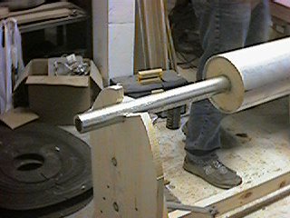
The forward end of our stacking spindle. The small tube is a piece of water pipe with 1-3/8" OD, and the large tube is an aluminum RS-15 tailboom. I'd originally designed a threaded aluminum lathe-turned adapter to mate the two. But when it came time, Steve just carved up a pair of adapter rings out of 3/4" doug fir. Works fine.
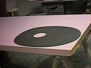
A masonite station template on one of our slabs of 3" urethane foam. We'd trace the station template on the foam, and rough-cut the foam blank using a paring knife.
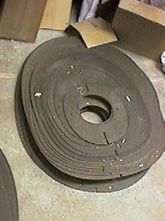
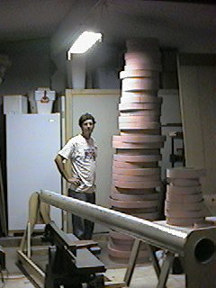
Our stack of 42 masonite station templates. I had these CNC cut by a guy with an engraving/carving CNC rig.
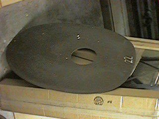
The troublesome Station 22 template. We found out later that I'd messed up the dataset for this one, so it came out 3/16" short. Steve had to make up the difference with microballoons and Bondo.
Steve tracing the inner contour of a foam blank. We'd cut the middles out of the larger stations to save foam and weight. We were able to use some of the cutouts for blanks for the smaller stations. In the end, though, we regretted cutting the centers out of all the stations. It didn't save all that much weight, and left Steve with a lot more foam scraps to haul to the dump.
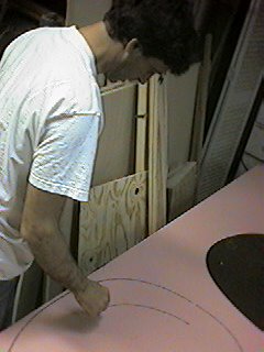
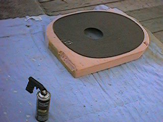
A typical station and blank. After the foam template is rough-cut, we'd glue it to the masonite station template with 3M 77 spray glue. After the glue set, I'd use the bandsaw to cut the blank to within about 1/16" of the template contour.
Steve and the stack of station templates and finish cut foam blanks.
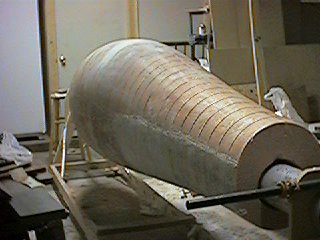
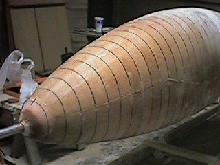
Fast forward to after the 20 April update. Here, we've stacked the blanks onto the spindle, rough-carved the foam, and have applied the first coat of fiberglass.
Same, foreward view.
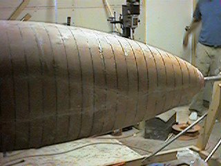
Side view, the very front.
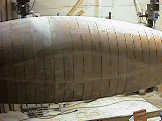
Side view, middle portion. The funny shape along the equator is where 50" wide fiberglass cloth wouldn't meet. We had to cut and apply separate patches there.
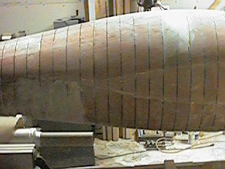
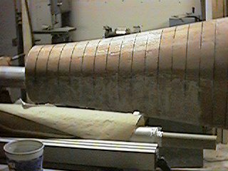
Side view, aft-middle portion. The off-color wedge at the point of maximum height is where I messed up the station 22 template and Steve had to compensate with extra bondo.
Side view, very aft portion.
page updated 08/24/01 all text and graphics copyright (c) 2001 HP Aircraft, LLC