This weekend we got the carbon horizontal stabilizer readied and closed, and I got some progress towards a display stand to mount it on when I bring it down to Tehachapi this coming weekend.
Here's our first two lost arrow ribs, which Brigitta unbagged and rough-trimmed this week.
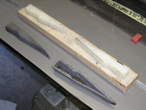
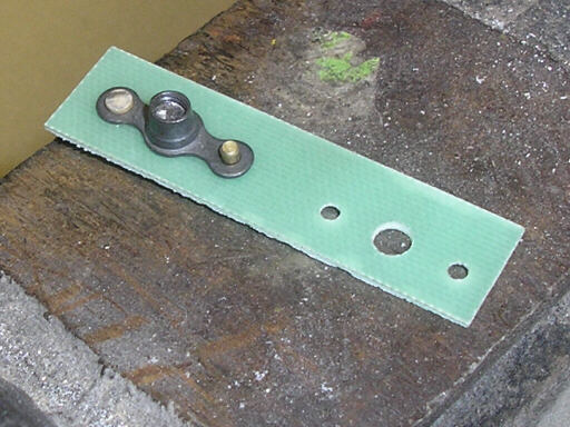
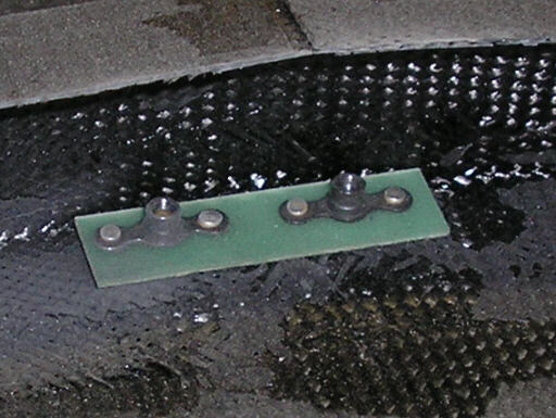
Friday evening 22 August 08: The parts for the anchor plate that secures the bolts that hold on the horizontal stabilizer attachment fitting. The aluminum fitting shown gets bolted onto the outside of the horizontal stabilizer at the apex of the V formed by the forward shear web. Inside the stabilizer I bond in a piece of fiberglass that has two anchor nuts riveted to it. I took these next few photos at the request of a rec.aviation.homebuilt poster who wanted to see an example of driving solid rivets without a rivet gun or squeezer. In this photo the plate is freshly countersinked (countersunk?) with the microstop countersink tool in the background.
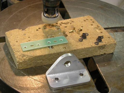
The plate with one anchor nut and two rivets fitted. Note that the rivets show only a little more than one diameter of shank beyond the parts to be joined. That's very near the minimum specified in AC43.13, but I'm not too worried since these rivets don't have to do much except hold the nuts in place for the installation and removal of the bolts. And besides, the operant guidelines of AC43.13 aren't how much shank protrudes before driving but rather the height and width of the shop tail after the driving. I've found I can generally get a nice shop tail with around 1.5 D of shank, so that's what I shoot for. The driving surface shown here is just the anvil portion of my bench vise.
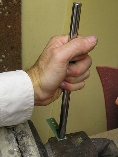
Getting ready to drive the rivet. The shiny rod is a high-precision custom-made rivet drift of case-hardened Unobtanium--not. It's actually the piston rod of a shock absorber I fished out of the dumpster of the auto repair shop next door. So far I've had really good luck making tools and fittings from discarded auto parts. After this photo I applied three strikes of a medium-sized claw hammer to the drift to set the rivet.
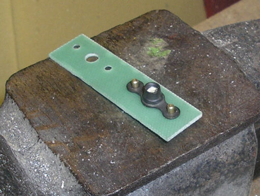
One down, three to go. Slightly overdriven, and with a bit of angle on it, but I'd bet good money this rivet would shear test to the 26 ksi you'd expect for an MS20426AD or MS20470AD rivet - which is probably more force than the fiberglass it's installed in would take.
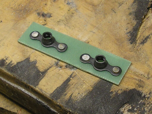
All rivets driven. The third from the left is probably too overdriven for a real structural application, but this is just an anchor nut attachment.
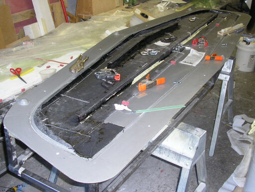
Here's the chaos that prevailed on the lower skin while readying it for closure.
Test-fitting the left lost arrow rib.
The anchor nut plate test-fitted in position..
Saturday morning, 23 August 08: Brigitta holds the lost arrow in position while we bond it in with fast-setting epoxy.
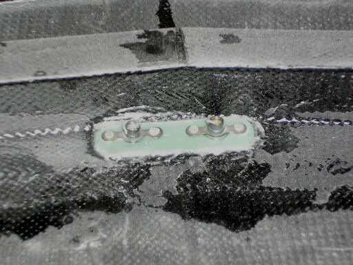
The anchor nut plate bonded in with the same stuff. Note that I've rounded the corners somewhat. I've also scuff-sanded the mating surface for better adhesion.
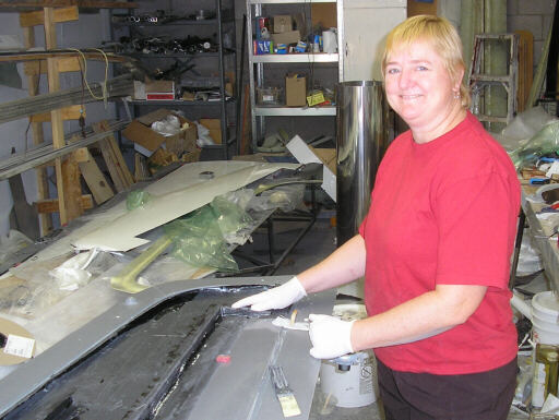
The lower stab skin cleaned up and ready for bonding. I've scuff-sanded all the mating surfaces and wiped them with acetone. We've scraped off as much tape residue as practical, and have secured the skin to the mold with the main fitting jig and bolts through the forward fitting locating holes. After this photo we spread bonding paste on all of the mating surfaces, dropped on the upper skin shown in the photo of Brigitta above, and then clamped on the upper skin mold to skoosh everything together.
And after we did all that we closed up the shop and got away for the afternoon. We packed the kids into our Subie adventure car and went down to our favorite swimming hole on a tiny branch of the Stanislaus river that winds past two small hydroelectric plants. And there we swam and sunned ourselves and jumped repeatedly into the river from a height of eight or ten feet that seemed more like 20 or 30 feet when we were doing it.
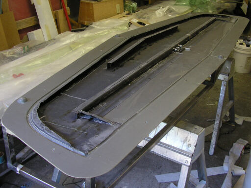
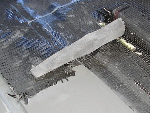
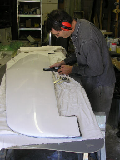
The following day (Sunday 24 August 08), the bonded stabilizer flipped over so I can start trimming it with the Dremel tool. Here I'm shortening the tightening stud.
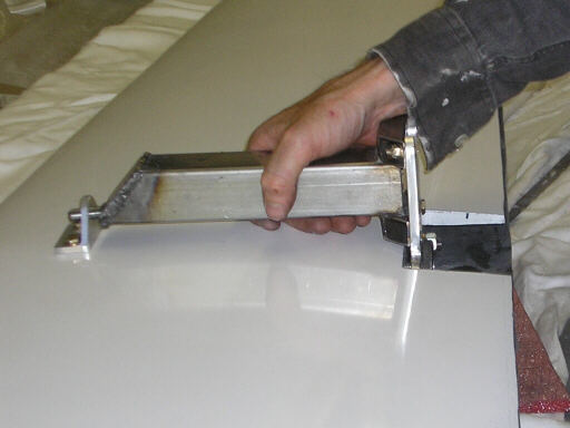
Later, with the forward attach fitting bolted on, test-fitting the part of the display stand that grabs onto the forward and aft fittings just like the fittings on the vertical stabilizer will.
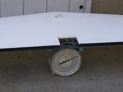
On the scale. The carbon fiber horizontal stabilizer weighs in at 9.2 lbs on my shipping scale, with the forward attach fitting in place but without the elevator hinges.
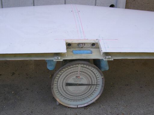
For comparison, the fiberglass version weighs in at about 13.1 lbs without the forward attach fitting but with the elevator hinges in place. That's about 43% heavier than the carbon one for similar strength and stiffness.
Homebuilt aviation is not for folks who don't try things at home.
page updated 25 August 2008 all text and graphics copyright (c) 2008 HP Aircraft,
LLC