Last weekend I did the scarf joints between the skins of the inboard and outboard sections for the left wing plug. By keeping a flexible schedule, I was able to also scarf both the upper and lower surface skins together, and fit in a pretty full weekend besides.
Having just reached a holding point in my projects at work, I took Friday, 23 April as a vacation day, and did the upper surface scarf in the Arnold shop. That afternoon, we packed up the car and drove over to Reno for the Air Sailing (http://www.airsailing.org) Spring Cleaning day, where I reprised my generally-successful 2003 performance of lubing the StackDoor hangar doors. I've developed a philosophy about dust and ball bearings: dusty oil isn't that good at lubrication, but it sure beats dust alone.
While working on the hangar door, I found that a couple of the top rail rollers had gone missing, and their shafts were just rubbing on the rails. I liberated one of the rollers, and found it to be an HMF N9R-10 ball bearing - generically speaking a double-shielded ball bearing that you'd call an R10ZZ. When I returned to civilization, I went looking for some of these. McMaster-Carr gets six bucks and change for them each; not bad. But then I found a set of ten of them on the glorious garage sale of Western Civilization called eBay; with shipping my winning bid came out to about a buck eighty each.
Anyhow, on Sunday we drove home down Interstate 80, stopping in Truckee for breakfast at the counterculture classic Squeeze Inn and again near Donner Summit to get in a couple hours of rock climbing at a local slab hangout. On Sunday afternoon we got home with enough daylight left to get up to the shop, flip the left wing plug, and scarf the skin joint on the bottom surface.
That left bottom scarf joint is probably my greatest disappointment since I discovered that the first set of outboards had been cut wrong. Having shimmed the plug sections to get the best possible fit between the sections on the top surface, I found a step of almost 0.035" in some areas of the joint on the bottom. Where it came from, I can't say for sure without template checks. It does fall within the allowable tolerance stack up for all the various bits. So I imagine that one section is a handful of thousandths tall, the other is a handful of thousandths short, and the step is the resulting difference between the two.
My recovery plan is to sand one side down through about one ply of glass, fair the other side out with microballoons spanwise over about 16", make the whole thing as smooth and fair as possible, and call it good enough. After all, one of the main theses of this project is that the precision required for a high-performance sailplane falls within the realm available to the conscientious and resourceful home workshop builder. That philosophical foundation comes from template checks of contest-winning front-line European racers that show some major differences between the expected and delivered profiles, and even between the profiles of the right and left wings. And if they can do that and still win, what I'm doing must be at least within the ballpark.
Here are the most recent photos of the project:
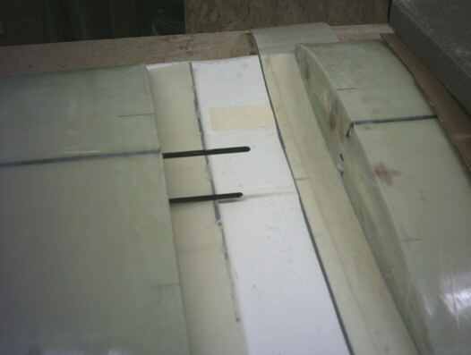
Saturday, 17 April. Here I'm preparing the structural splice between the carbon stiffeners. I've opened up the tunnels in the inboard section, and bonded the splice strips into the tunnels on the outboard section.
I'm preparing the alignment between the inboard and outboard sections.
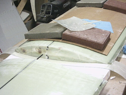
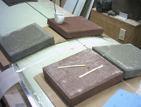
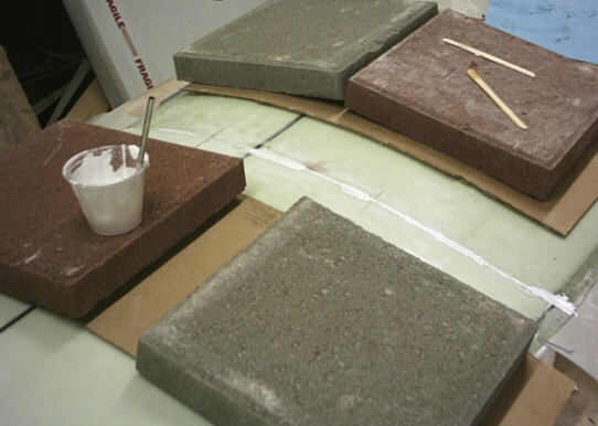
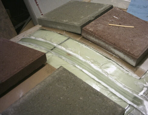
I've buttered the mating faces, aligned the sections, and drawn them together. The cup is full of the left over microballoons from the buttering.
Same topic, different angle.
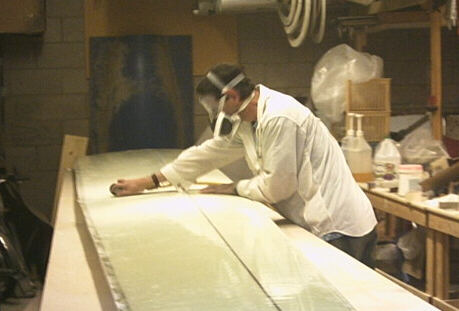
Friday, 23 April, scarfing the upper surface skin.
Sunday, 25 April, scrambling around the back of Kindergarten Slab to set a toprope for some slab climbing. That's me with the red rope bag; in the blue is a climber named JD who loaned me a couple of slings for the anchors. I also got to do some fun pendulum playing, pretending I was diving for Harding's stovelegs.

Later that afternoon, trenching the scarf for the lower surface using a right-angle die grinder and 2" Roloc sanding disks.
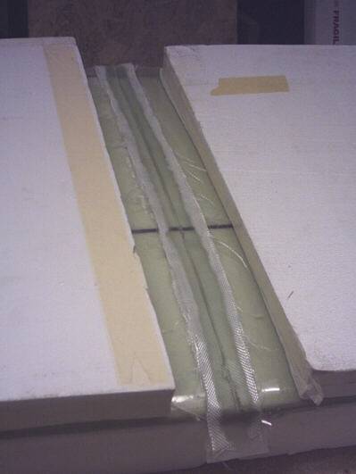
The taped lower skin scarf joint. The styrofoam shucks are just there because it was the easiest place to put them to keep them out of trouble.
page updated 29 April 2004 all text and graphics copyright (c) 2004 HP Aircraft, LLC