This last weekend was kind of a homecoming for me. Since I went up to Brad's the prior weekend to work on Glidair stuff, I haven't been home for nigh on two full weeks. Nor had I really had a good night's sleep, what with my real career being a bit hectic, climbing at the local gym three evenings a week, and hanging out helping Steve Smith on his latest projects.
So when I got home, it was great to be there, but it couldn't last. Up at the crack of seven AM on saturday, and thence with the daughters to Sutter Creek where the Brownie troop was touring a dormant gold mine.
I've been in caves, lots of them. Lava tubes, limestone caverns, all fascinating, quiet, peaceful collections of air and space below the earth. Been there thousands of years, probably to stay a thousand more. A mine is something else entire. Brutally carved from unyielding stone, it is a temporary place of temporary enrichment, steeped in disharmonious adrenaline and misery. Not that we don't need such places, or that they shouldn't exist. Just that I found little there to enrich the soul - a nice place to visit, but I wouldn't want to work there. Somehow gold fever never took root in me.
Anyhow, that plus lingering exhaustion pretty much shot my Saturday in the foot, and it limped off to bed to read Fred Pohl space operas.
Sunday, I sprang up, changed all eight brake pads on the wife's Volvo 745 (Girling front, but don't tell'em ATE ["ah-tay"] rear or it'll just confuse them), pulled the LH codes (1-4-4 and 3-1-1, both intermittent, neither fatal), then finally headed out for some HP shop time.
But somehow we didn't get right there. First we took a short detour to check out a climbing crag near Avery, which involved about twenty miles of driving on rough gravel roads and a detour down to a small but pretty concrete plug dam on the Stanislaus. Then to the shop.
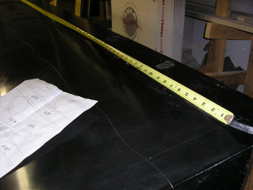
What we did this time was mark out and scribe the location of the flaperon hinge line on the bottom right wing mold. And how we did it was essentially a visit to the stone age, except with monofilament and measuring tape. After much fretting about putting the hinge line exactly at the 87.00% chord, I came to the realization that 0.030" or even 0.060" off matters almost absolutely not, so long as the lines are relatively straight and both wings look about the same.
If you've handled aluminum piano hinge, you know that it's kind of important to make hinge lines straight. Hinge lines don't like to go around corners, and when you try to make them, they convert themselves from mechanisms into rigid structures.
However, so far as sailplanes go, the important thing to remember is that there are no straight lines, not even hinge lines. Once you apply 1g or so to the straight wing with its straight lines, everything is bent out of line. When you watch an ASW20 do a finish pull-up (like they did back in the old days before beer-can gates), look at what happens to the wing and the flaps and the ailerons and their hinge lines: they all bend; and on the early ASW20s they bend a lot. Having handled a piece of aluminum piano hinge, you might wonder, how do they do that?
The answer is, forget about the aluminum piano hinge. It's useful and good and valid, but not instructive about composite sailplane hingelines.
Instead, consider the speedometer cable. The old fashhioned kind, like they still use on airplane tachometers. Not the electrical ones like the ones on my 740s, that log their 3-1-1s in the control computers when their electrical connections drop a few electrons.
A classic spedometer cable is a collection of steel fibers that transmits torque even when it is bent rather sharply. It works because so many of those fibers are on the bias, forming little spirals around the axis of the cable. The speedometer cable transmits torque as tension and compression in the bias fibers, not as torsion of the individual fibers as a straight or shallowly twisted or braided cable would.
Sailplane wings, and sailplane control surfaces are exactly the same. They are rather limber in bending, but are rigid in torsion because their skins are primarily bias fibers.
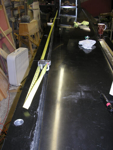
So, anyhow, this weekend we scribed relatively straight lines in the mold where the hinge line will go. The lines are as straight as they need to be, and in fact are as straight as the hinge line it represents will ever be.
Another thing we did was to make a first article part for the landing gear control handle. This handle appears in a sketch I posted last Update or so. Because it's in plain view I took some trouble to match it aesthecially with what I want the interior to look like. I also used a nice ball bearing with it because I want it to feel smooth and authoritative.
Well, here's the pictures:
We start mapping out where to put the ends of the flap and aileron hinge lines. Because the root fillet adds a big swoopy blob at the inboard end of the rib, it isn't a good candidate for a reference point. Instead, we decided to reference all wing dimensions starting at the kink at the leading edge at sta.152" between the inboard and outboard tapers. Once we isolated that kink, we drew a longitudinal line back to about 87% chord, and mapped the hinge line inboard and outboard from there.
Once we located the hinge line, we denoted its location by drawing a physical line in the tooling coat of the mold using a carbide-tipped scribe. While this is somewhat of a desecration of the surface, it's a minor one at worst. In the finished parts it is embodied as an "outie" in the gelcoat that will sand right off.
Then I got to work making the gear lever. Here's a re-post of the system sketch from the last Update. I decided to make the lever about an inch longer that is shown here, but of the same basic size and geometry. Note the extra lightening hole. As to why include the lightening holes at all, it's basically because I think that they look cool. I wouldn't use them on the inboard end of a Monerai wing spar, but I consider a landing gear retraction handle to be fair game:
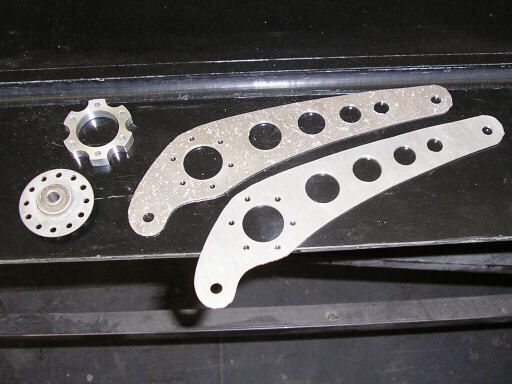
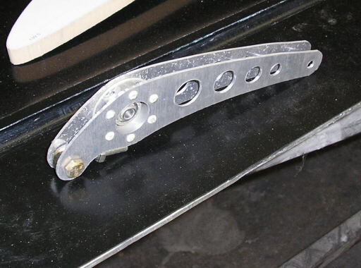
I started by printing out the handle design from the earlier sketch, spray-gluing the printout onto a chunk of masonite, scribing the outline and hole centers onto an aluminum blank, then gang-sawing four copies on the bandsaw. You see two of the copies here, drilled up with their lightening holes and rivet holes. Here you also see the bellcrank bearing, and the bellcrank bearing spacer, one of four or five I made in my father in law's machine shop back when I was cleaning up the aileron circuit of my old HP-11a. I made similar spacers for the HP-18 center stick retrofit project, but not with this level of finish.
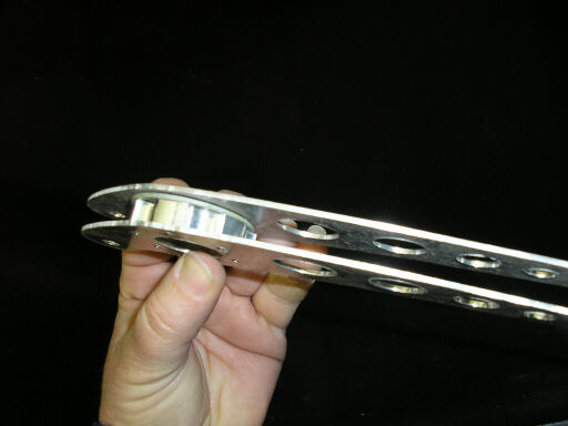
Brigitta shows how the whole mess stacks togehter. I decided that the handle should support its rod end in double shear because I wanted the handle end of it to be fairly limber in bending. The idea there is that the handle end will engage a pin set in the cockpit sidewall, and the pilot disengages the handle from the pin by bending the handle slightly inboard. Bending the handle to disengage it is a bit hokier than a precision-machined release mechanism, but it's also lighter, simpler, and more reliable.
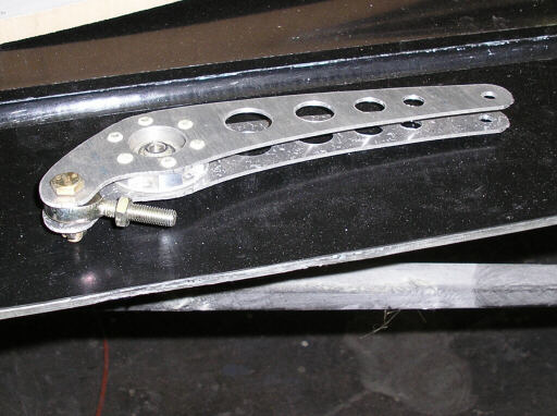
Here's the finished handle after riveting the whole mess together with MS20470AD4-something rivets. I didn't have any AD4 rivets the right length so I took some that were too long and cut them to size with my rivet cutter. I set the rivets with a hand squeezer that I got at some surplus sale or other. I could just as easily have set them with a hammer and a drift, though, if I could have talked Brigitta into holding the part. But she knows how accurate I am with a hammer, and wisely headed out to get the car warmed up.
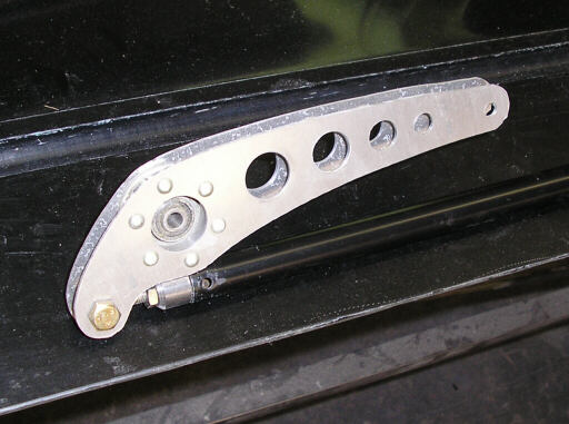
Here's how it looks with its 5/8" OD steel push-pull tube installed. The PP tube will be hidden under the cover of the right-side armrest.
page updated 29 January 2007 all text and graphics copyright (c) 2007 HP Aircraft,
LLC