In the last two days we've made a set of the horizontal stabilizer shear web channels, fitted them into place in the lower skin and in the internals jig, and then bonded them into place. We also shmoo'd in the taper pin sockets for the aft mount, and drilled the forward shear web for the captive nuts that anchor the forward mount. Happy birthday to me!
Tomorrow we're scheduled to take the day off for a trip into Yosemite, with a bit of hiking and cragging, and then I'm back to work in the Silicon Valley.
Here's some photos, in chronological order. There's rather a lot of them:
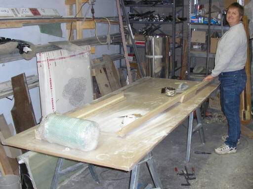
On 29 December 2007, Brigitta preps the shear web channel mold. This is strctly lo-fi stuff, table-sawn MDF coated with packing tape for mold release.
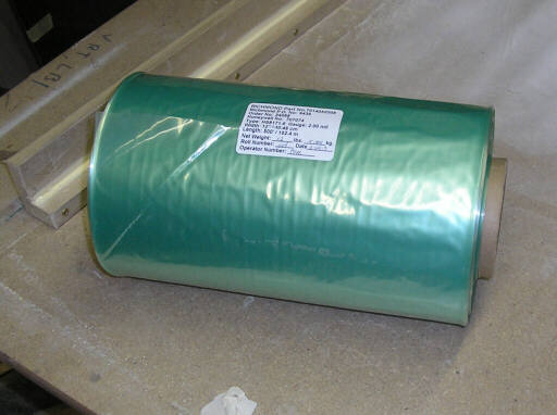
My latest consumables purchase: a 500-foot roll of 12" wide nylon vacuum bagging tube. You only have to seal the ends.
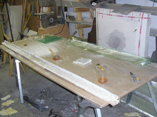
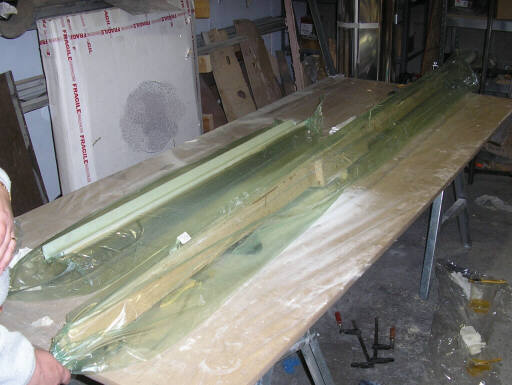
Laying up the shear web channels. The short one is done and waiting in its bag, the long one is under way.
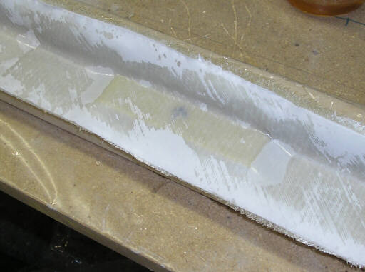
The center of the long (aft) shear web channel, showing how I've included the Garolite reinforcement where we'll pot in the taper pin sockets. The top layer is polyester peel ply. There's a lot of bubbles below the peel ply, but the vac bagging will suck them out.
The next morning (30 Dec 07), unbagging the shear web channels. We discovered a neat trick for separating the vacuum bag: just inject pressurized air into the vacuum tap and the bag assumes a circular cross section and releases the part.
The molds and parts, out of the bags.
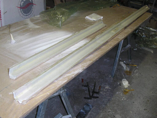
The parts released from the molds. Packing tape really does make a nice surface and mold release for stuff like this. We used peel ply as both first and last layers so that the parts would have nice rough surfaces on both sides.
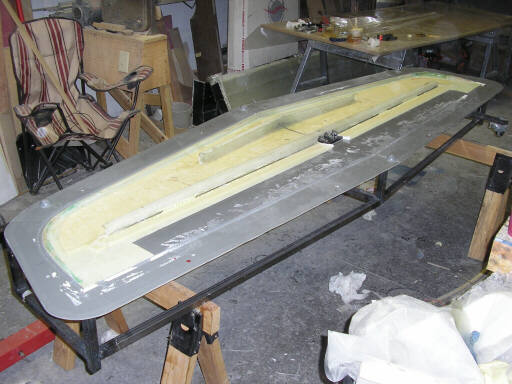
The lower skin, mold, and internals jig with the aft shear web fitted into place.
Marking the hole centers for the taper pin sockets and for the mounting stud. I'm using a transfer punch, hammering the end of the punch while holding a bucking bar against the back side of the part.
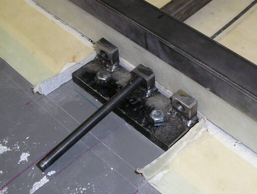
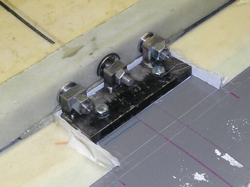
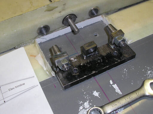
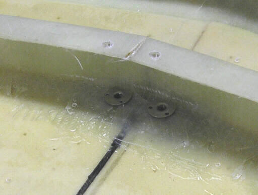
Here's the taper pin sockets and the mounting stud fitted into place. The taper pin sockets are loose in their bores, and the bores are tapered out on the back side to make it easier to pack shmoo in between the socket and thte bore. The ring at the base of the mounting stud is the flange of a T-nut.
The taper pin sockets on their locating jig.
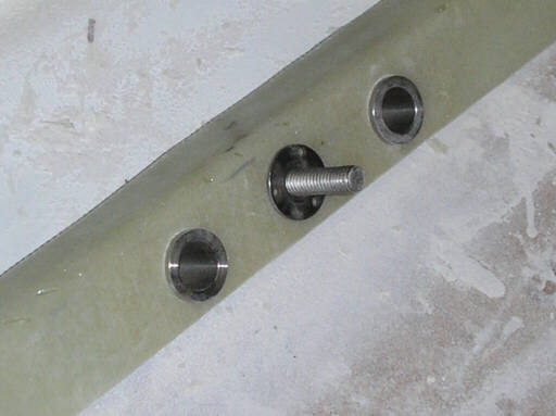
View of the forward face of the aft shear web channel. Note the gap between the taper pin sockets and their bores.
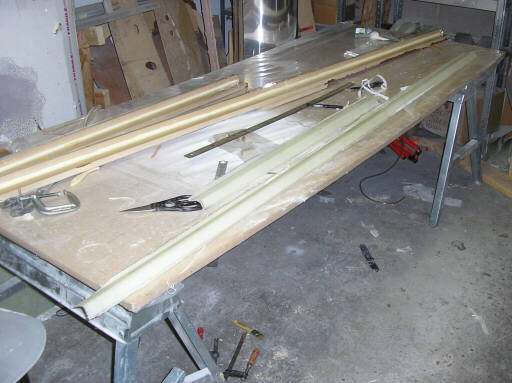
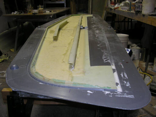
The following day (31 Dec 07), now the two halves of the forward shear web are fitted and clamped into place.
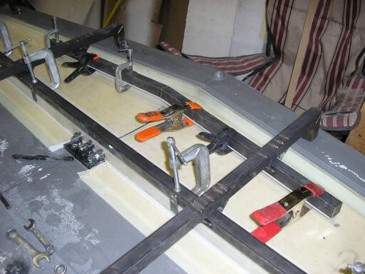
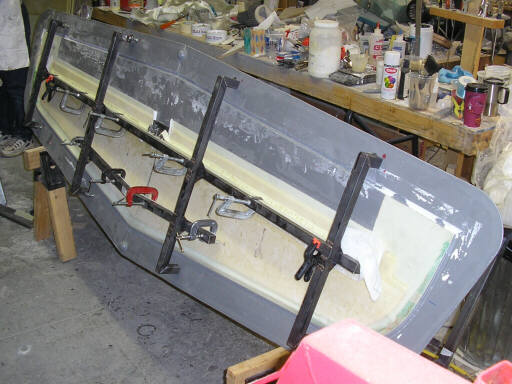
Preparing to bond in the two shear webs. We've already bonded in the aft shear web, and have tipped the mold up on edge to make it easier to bond in the forward web halves.
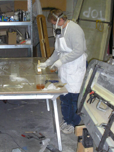
Brigitta pre-wetting the bonding tapes. Note the characteristic salmon color of the Jeffco epoxy resin.
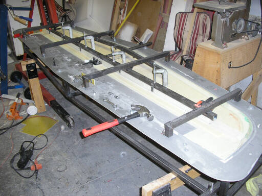
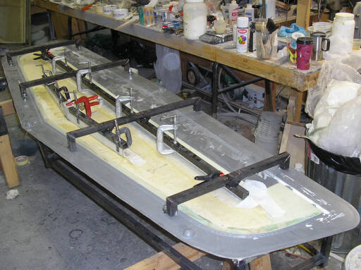
Both shear webs bonded into place. The peel-ply tapes help keep wick up extra resin and keep the edges clean.
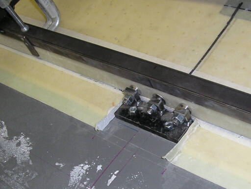
The evening of 31 December 07, the parts are cured enough to remove the positioning fixture and do some cleanup.
The taper pin sockets and locating fixture.
End-on view of the lower skin and shear webs. This is pretty messy work, I'm not particularly proud of the drips and smudges of resin. However, since this will be a static test article, I feel obligated to approach it with somewhat casually to duplicate representative build quality.
Liberating the taper pin socket fixture. It took a bit of light hammering to release it. If you've ever assembled an LS3 or similar, the drawing will show some familiar-looking parts. I've not directly copied any particular part, but I did follow the same general arrangement.
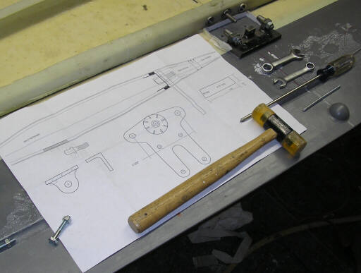
Closer-up of the fixture, sockets, and mounting studs.
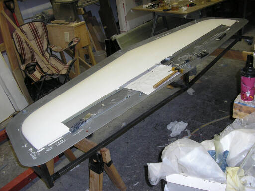
Having gotten this far, I couldn't resist. We dug out the upper skin and set it on the lower skin with internals. It fit well. We'll probably mate the skins like this, using a few clecos along the leading edge and setting the internals fixture on top.
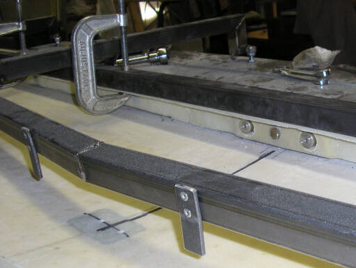
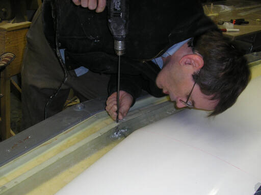
I've drilled the forward mounting angle bolt holes 3/16" up from below, through the original holes. The holes in the upper shear web let me drill down 1/4" through the part but not the mold. Off to the left are the T-nuts that we'll bond into the inside to anchor the bolts for the forward mounting angle.
Drilling the bolt holes up to 1/4" to accommodate the T-nuts.
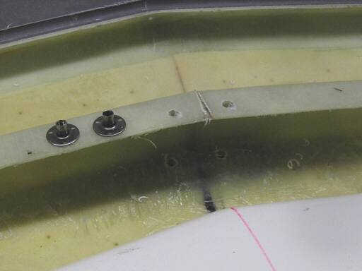
The T-nuts for the forward mount angle in place. We'll put a tape over these the next time the heater is running.
Homebuilt aviation is not for folks who don't try things at home.
page updated 31 December 2007 all text and graphics copyright (c) 2007 HP Aircraft,
LLC