Last week I was up past midnight on three weekdays (one at work, two working on Steve Smith's RV-8), and as a result I had a really slender fatigue margin by the time the weekend rolled around. As a result, I ended up having to spend more time in bed than otehrwise, and consequently got less done at the shop.
However, I did manage to make a mockup of the forward roll bellcrank, change my two stick hoists to rotary cranks instead of ratcheting levers, and make a new wing inboard template for the wing mold washout survey.
I also did some climbing gear proof loading that I'd promised to do months ago. Those videos are up on my Breakotron YouTube account.
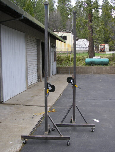
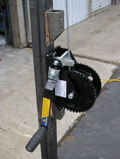
Here's the two stick hoists with their new crank winches. In service, we found that the lever-ratchet come-alongs that we'd used earlier were slow, difficult to lower with, and didn't have enough cable to lift a mold from the floor up to the top of the mold stack. So this weekend I changed them both over as shown here.
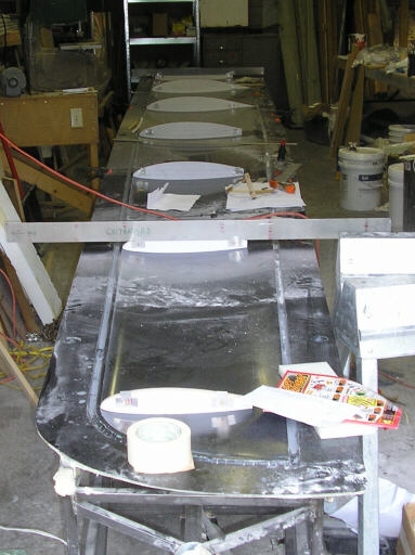
Here's the bottom left wing mold with the survey templates in place. What's new here is a template at about 6" outboard of the side-of-body junction. The template I made for the actual side-of-body profile didn't work since that station has been submerged by the side-of-body fairing. So I'll be measuring incidence and washout from the wing station about 6" outboard of that. According to this survey I have some work to do at the inboard end of the molds to remove a bit of wash-in that creeped into the tooling. No big problem, I'll just cut a couple of the inboard aft diagonals on the truss and weld adjusters into them, as I should have done when I originally made the mold support trusses.
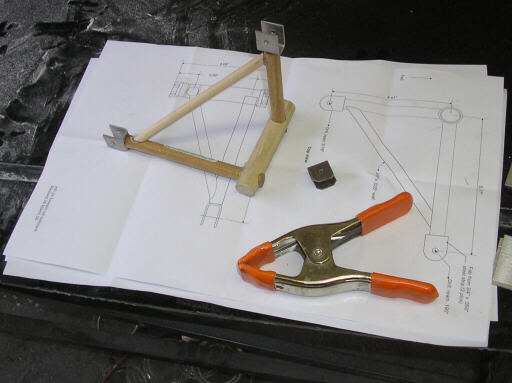
This forward roll bellcrank mockup is so we can validate fitment and to make jigs to weld up steel flight articles. This week I'll be doing some work on the lathe to make the bearing cups for the ends of the torque tube, and making the spacers that go between the bearing inner races to prevent clamping loads on the axle bolt from binding the bearings up.
Meanwhile, Brad Hill has been hard at work on the forward fuselage and cockpit internals parts. Here's a couple shots of the first article of the #3 bulkhead.
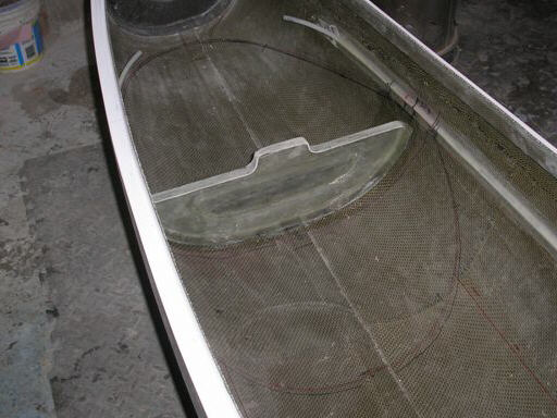
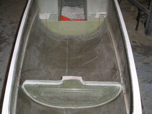
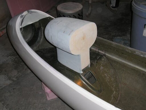
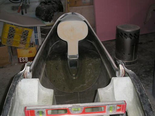
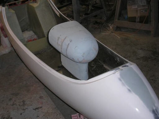
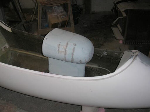
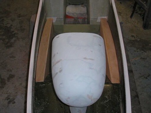
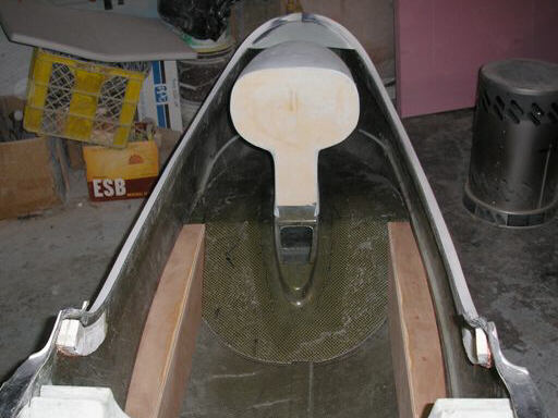
Four photos of the instrument pod plug in its current state. Note that it now extends a little further aft than in earlier photos. That's so that the mold embodies enough of the profile so that we can have the hood extend an inch or so aft of the instrument panel as a glareshield.
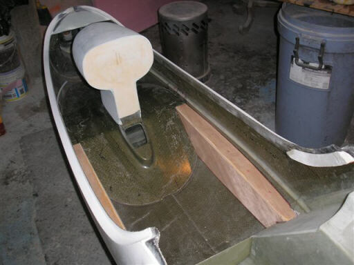
Three photos showing mockups of the cockpit side angles. These mockups represent the composite angle stiffeners that get bonded onto the fuselage. Sailplane crash tests show that good, stout stiffeners like we're planning, well-bonded (not just screwed) to the fuselage interior can absorb a lot of energy. However, the window of impact energies that good design and construction can protect pilots from is relatively narrow. So it's still best that you not crash.
Homebuilt aviation is not for folks who don't try things at home.
page updated 31 March 2008 all text and graphics copyright (c) 2008 HP Aircraft,
LLC