Mostly I've been working on those darn airbrakes. I am now pretty comfortable with the design that I've worked out. I think it will work OK, will fit into the wing OK, and (most importantly) that we can fabricate and assemble the parts without any particular heroics. I think we might have to do some tweaking to get all the clearances right, but I don't think that will take any great deal of trouble.
I'm also working on the root ribs, figuring out where we'll mount the autoconnect arms onto them and getting squishes of the profiles.
The next big mechanical puzzle will be the outboard flaperon drive bellcrank. That's another intensely 3D part that is best developed in situ to capture the subtleties of its location and geometry.
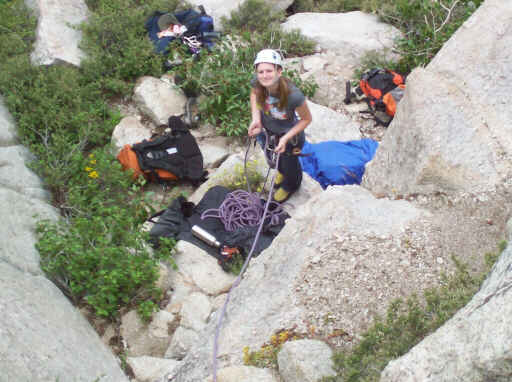
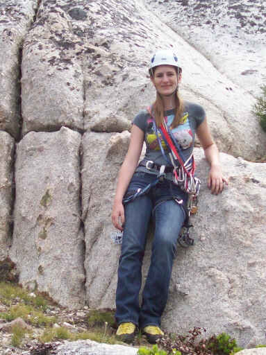
On 18 July, climbing with Alia at Chipmunk Flat on Highway 108.
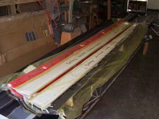
On 19 July, Rearranging the shop after ADF 10. Here's two flaperon skins still in their molds.
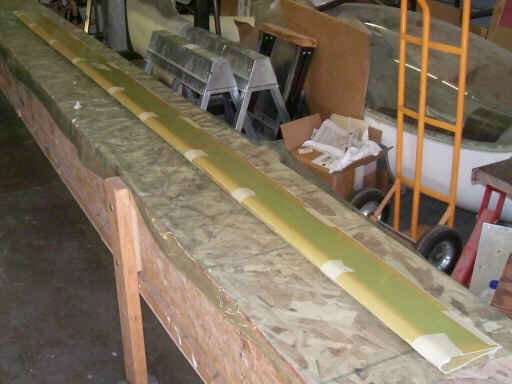
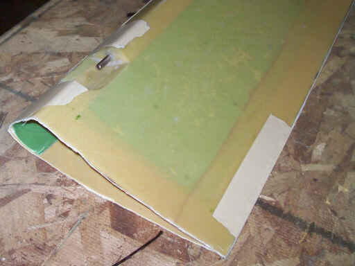
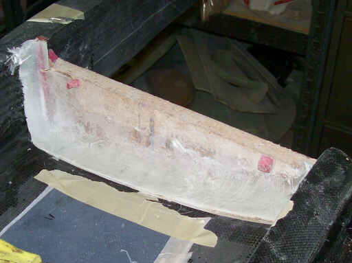
Three photos of one of the inboard flaperons that Doug and Brad made during this latest ADF.
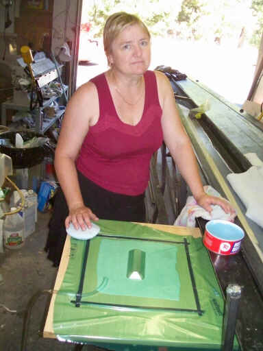
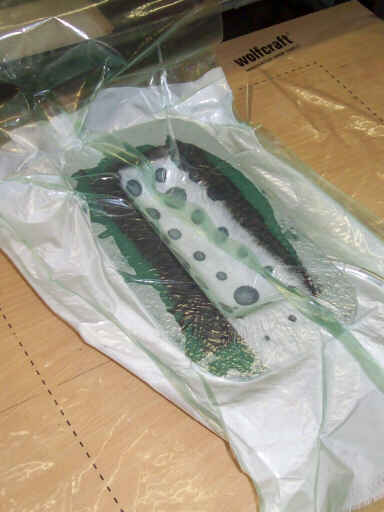
On the afternoon of 24 July, Brigitta waxes the form for the mold for the aibrake arm forward anchors. This is a generic mound shape that we'll cut to size, embed anchor nuts in, and bond onto the aft wall of the wing spar. We're using an experimental vacuum-filmed molding technique that I read about on Jim Marske's Web site.
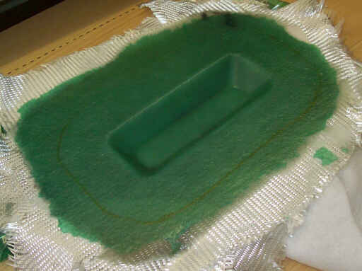
The next day, the mold unbagged. This didn't work out as planned; even though we waxed the stretch film over the form it would not release from the epoxy. The next time we try this, I will use thin visqueen or even just saran wrap instead of stretchalon for the vacuum film.
Later that day, making the first part in the mold. I spent all the rest of the day cutting and shaping the steel tubing for the airbrake arms.
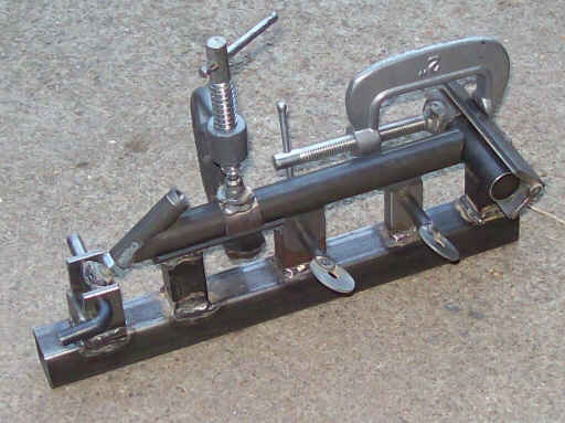
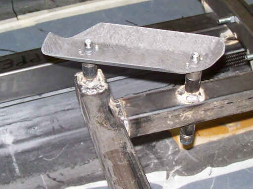
Early that evening, the first full set of parts for the outboard airbrake arms. Note the microstop length adjustment for fine-tuning the four-bar geometry of the airbrake system.
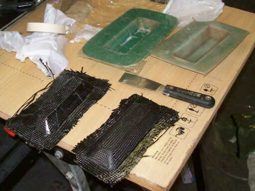
On 1 August, the first two parts from the airbrake anchor molds, and a second copy of the mold we made to supplement the first.
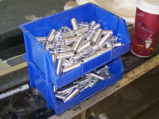
Doug and Brad left me these storage bins after the last ADF, probably as a hint that I need to work more on organizing the shop. Here I've filled a pair of them with threaded bosses for attaching 1/4-28 and 3/8-24 male shank rod ends to the 5/8" OD aluminum tubing we're using for most of the control system push-pull circuits. I shopped these out on mfgquote.com and got pretty good prices on them so I ordered 75 each.
The first set of anchors, trimmed to size and fitted with anchor nuts.

The inboard and outboard anchors attached to the locating fixture.
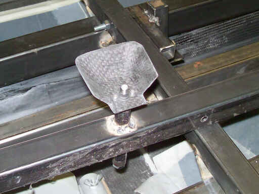
The fixture mounted on the spider and tagging the anchors onto the spar. They'll later get secured with two extra plies of carbon.
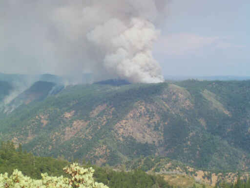
That afternoon we drove up to a brushy knoll that overlooks the Stanislaus river canyon to have a look at the Knight fire burning on the far side.
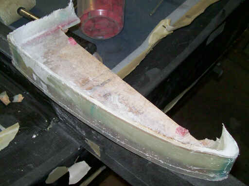
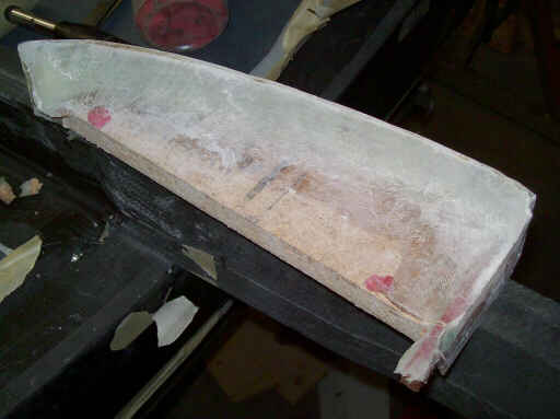
The morning of 2 August, three photos of the half-squish that I'm making to capture the profile of the left forward root rib. The plane of the top edge of the web roughly corresponds to the chord line. I will make matching half-squishes on the lower skin, and later bond the half-squishes together using either a mating fixture or by matching the two wing skin molds together.
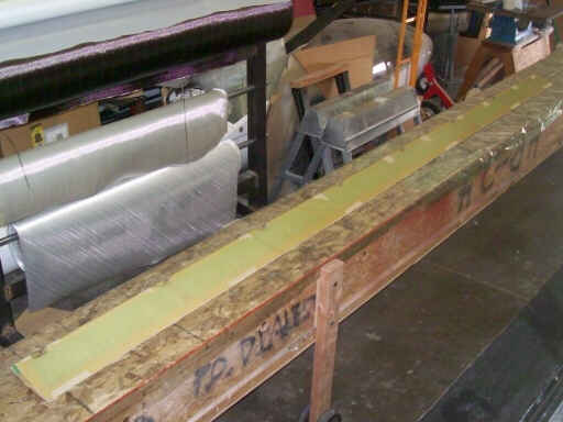
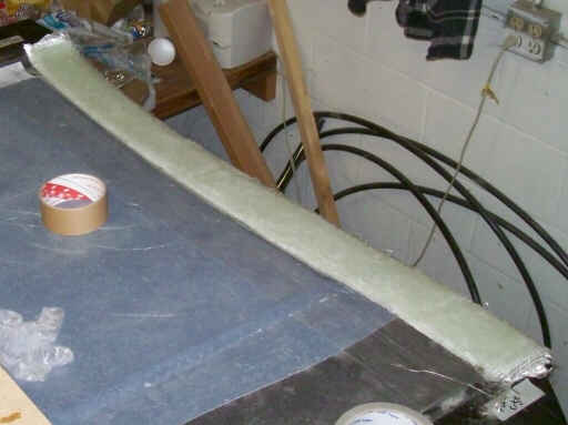
This thick strip of fiberglass at the inboard end of the lower wing skin will become the lower flanges of the half-squishes for the root ribs. Later I'll make two-piece molds for the root ribs. I'm using aluminum furnace tape and clear packing tape for mold release.
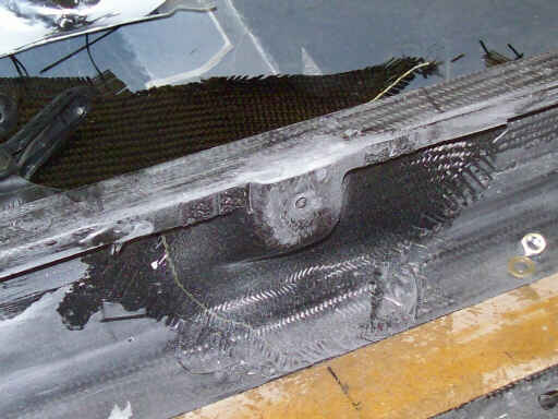
That evening, the outboard airbrake arm anchor, still needing some cleanup but ready for testing the airbrake arm geometry.
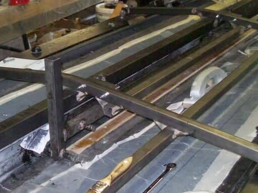
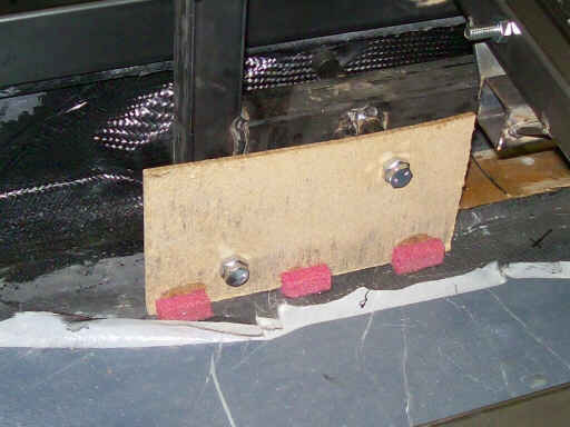
Here I've put the locating fixture back onto the spider, and I'm using hot melt glue and PVC foam chocks to tag down a piece of masonite that represents the aft wall of the airbrake box where it supports the inboard arm and also the overcenter bellcrank.
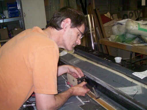
Fitting the arm in place and evaluating the swing against the location of the slot in the upper surface.
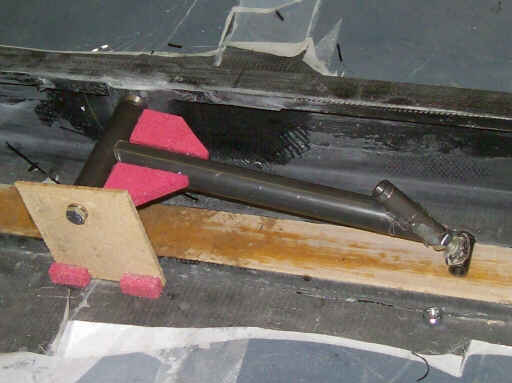
The airbrake arm (temporarily assembled with hot glue and more PVC foam chocks) in place at the outboard anchor station.
Homebuilt aviation is not for folks who don't try things at home.
page updated 3 August 2009 all text and graphics copyright (c) 2009 HP Aircraft,
LLC