Over the Christmas holiday I chipped away at all the little stuff that needs to have happened for us to close a pair of wings at Akaflieg Douglas Flat 12. Mostly I made and installed the big parts of the right wing airbrake box. I also worked on the flaperon drive, but the mechanism I've chosen for that is proprietary, so, sorry, no photos of that.
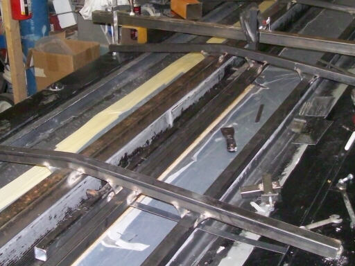
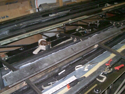
On 19 December, in the wake of ADF 11 I had both upper wing molds and skins in the heated bay, so I decided to go ahead and work on setting up the airbrake pivot jigs while I had easy access to both airbrake areas. That way I could easly transfer measurements from one to the other and make them about the same. In this photo I'm positioning the airbrake pivot jig in space where it belongs in the right wing.
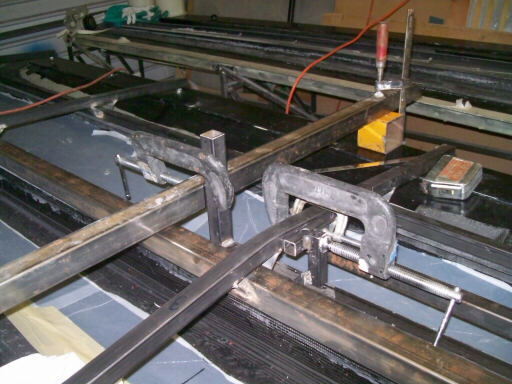
On 20 December, continuing work on orienting the airbrake pivot jig. The left C-clamp holds the inboard end in position on a reference bar that parallels the chord line. The right C-clamp positions the weldment that mounts the pivot jig to the spider.
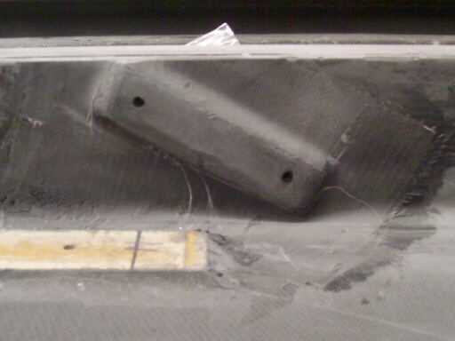
Here I have the pivot jig mounted to the spider and I'm positioning the right outboard airbrake arm forward anchor against the wing spar.
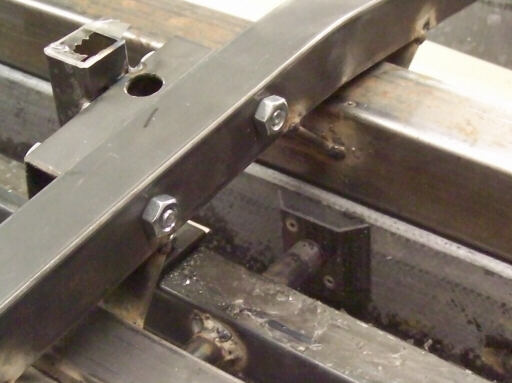
On 26 December, I installed anchor nuts in the right inboard forward airbrake pivot anchor and positioned it against the wing spar using the airbrake pivot jig. In the foreground is an extra forward pivot anchor blank that I didn't use.
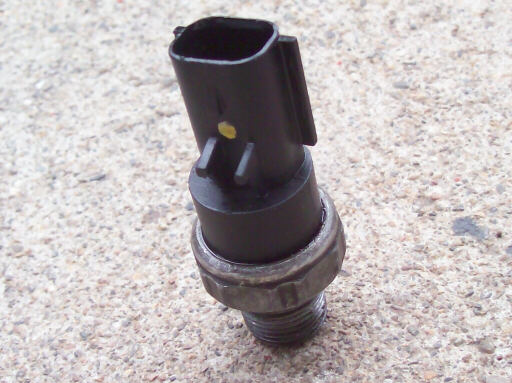
Earlier that day I had removed the oil pressure switch from the Dodge Neon to diagnose a pair of anomalous oil pressure indications. I'd be sitting at a stop light and the oil pressure light would come on briefly, then go out on its own. This happened twice, one week apart. There's plenty of fresh oil in the pan, and no other indications of any oil pressure problems, so I decided to remove and check the switch. The switch is completely hidden from view from both above and below, so you have to work by feel. You must have a 27mm (1-1/16") six-point socket to remove the switch. This photo shows the removed switch.
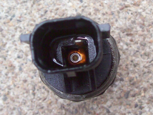
And this photo shows how I knew there was a problem with the switch. As soon as I disconnected the electrical connection, oil dripped out. That tells me that the switch had an internal leak, and its indications are suspect.
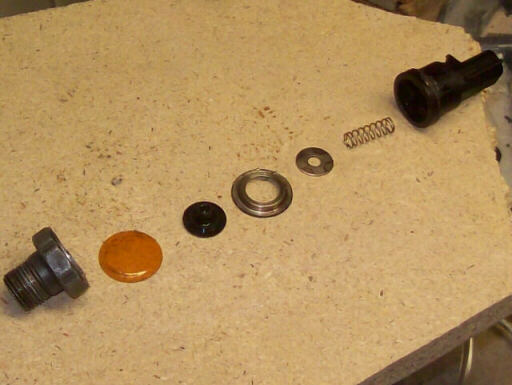
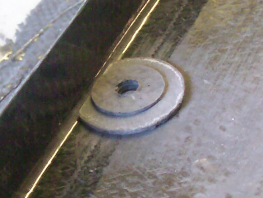
This photo shows the oil pressure switch internals. The yellow disc is the elastic membrane, it is crimped into the body of the switch (the leftmost part) by the ring in the middle. Oil pressure inside the body bulges the membrane and lifts the black plastic plunger, which unseats the washer from the ring and breaks the electrical connection between the wire to the switch and the grounded engine block. In this unit, oil was leaking between the membrane and the body.
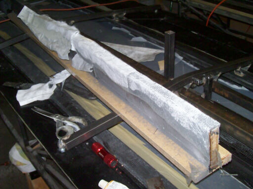
Back to work on the glider! Since I was ready to start making the right airbrake box, it was time to get out the rear wall angle that Brigitta and I had laid up on 30 August 2009 (See the 21 September 2009 Update). Here it is still swaddled in the breather and peel ply we applied on that hot summer day.
And here it is unwrapped, rough-trimmed, and marked (twice) for trimming to height.
On 29 December, I removed the right inboard spider and drilled the holes in the pivot jig through the aft wall of the airbrake box.
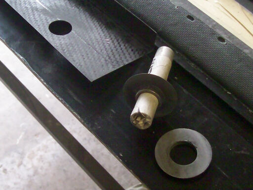
Here I am preparing a pair of carbon disks to reinforce the aft wall of the airbrake box where a bolt anchors the airbrake arm pivot. Whenever I cut away a piece of carbon scrap that is at least 18 oz thick (three ply of 6oz/yd^2) I save it and cut disks out of it using a holesaw for reinforcements like this. They are faster and easier to apply than a bunch of plies of laminate.
Here I'm preparing the airbrake drive crank bearing holders.
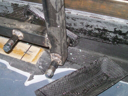
This photo shows how I've tagged the inboard forward pivot anchor against the spar using a pair of short tapes.
And here at the outboard pivot I took a different tack; I just applied masking tape around the edges and filled the space between the anchor and the spar with shmoo.
On 30 December, the two bolt holes in the aft wall were cured and ready.
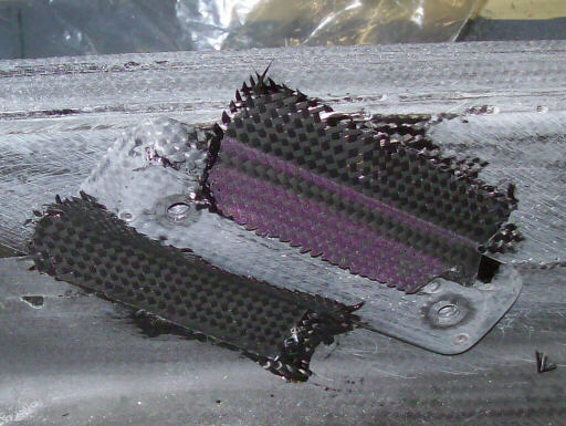
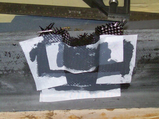
The inboard anchor jig tapes are cured, and deadly spiky.
And the outboard anchor is shmooed onto the spar.
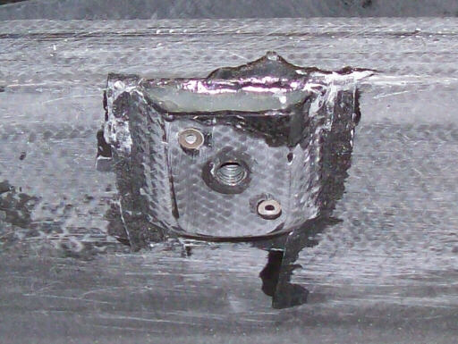
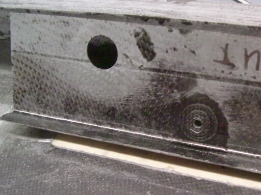
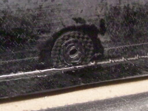
Here's two photos of the anchors after some cleanup, and the installation of a set of setscrews that keep epoxy out of the anchor threads.
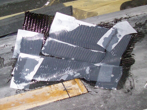
And here's two photos of the anchors securely taped in with two patches of 6oz carbon each and swaddled with peel ply.
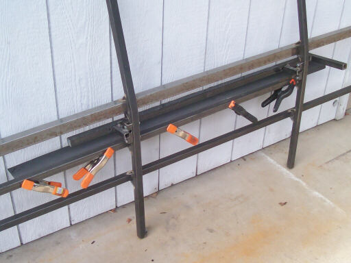
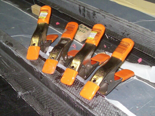
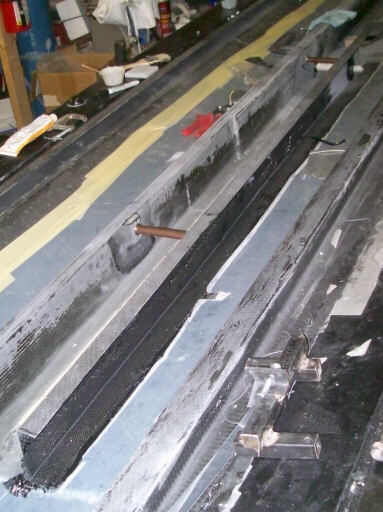
While I had the resin handy, I went ahead and spliced the inner and outer portions of the drag spar together. The clamps hold on a strip of aluminum that I used to temporarily keep the splice fron sagging away from the undersides of the drag spar sections.
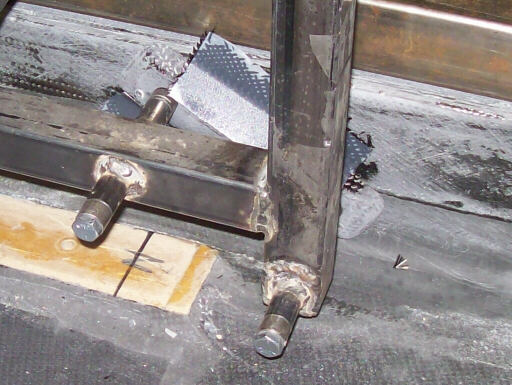
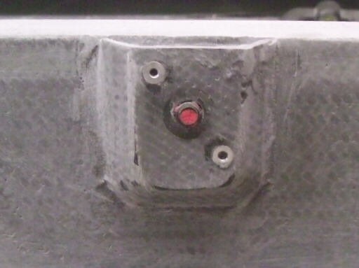
On 31 December, the forward anchors are cured into place; here's the inboard one as it looked on removing the peel ply.
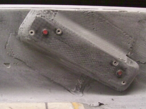
And here's two photos of how they looked after a bit of cleanup sanding. If I really cared how they looked I would have thinned a bit of resin with a touch of acetone or denatured alcohol and brushed it on as a varnish to bring out that nice carbon fiber look. But I don't, so I didn't.
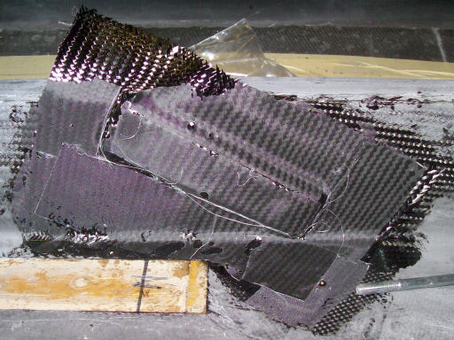
Here I've reinstalled the spider and the airbrake pivot jig, and I'm using it to position the airbrake box aft wall which I'm taping in place with two ply of 6oz carbon.

We spent 1 January 2010 in Yosemite, which has become sort of a family tradition.
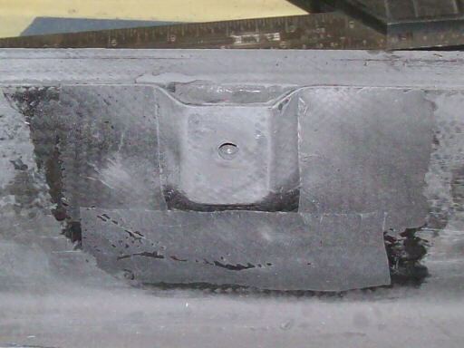
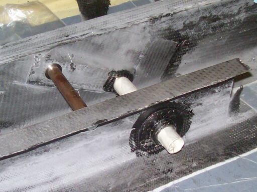
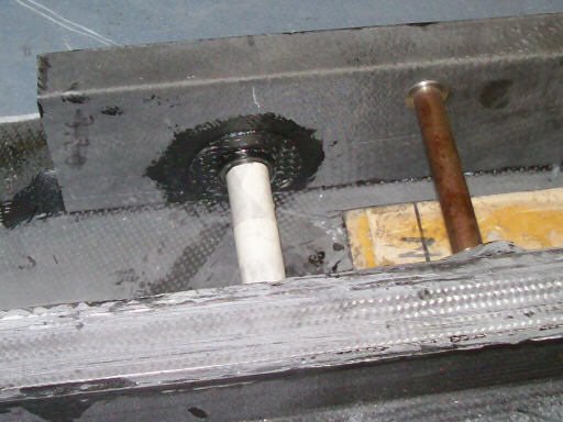
On 2 January 2010, here's the airbrake box aft wall cured into position, with the drive crank pivots also bonded in. The brown tube is one of the airbrake arm pivot tubes, in this situation it is holding the airbrake box aft wall in alignment while the crank pivots cure.
And here's the whole airbrake box.
Another shot of the inboard pivots.
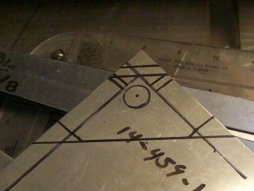
Here I'm making a template for a piece of steel that serves as the airbrake drive travel stops.
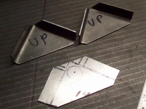
Here's two steel parts and the aluminum template.
Here's how I set up my brake to make the part. You can see that I have marked the template outline on the bending leaf, and I have removed one of the pan teeth so that the first flange doesn't interfere with the braking of the second. Note also the radius shoe that keeps the bending radius generous to prevent cracking.
Here I've holesawed the 7/8" hole for the tube that the stop welds onto.
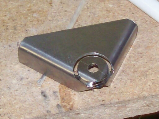
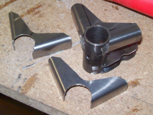
This photo shows the drive crank with the prototype hot-glued on, and the two actual parts that will get welded to the actual drive cranks. Note that I've trimmed away a lot of the extra material along the hypotenuse of the triangle. Good performance comes more often from what you leave on the ground than from what you take with you.
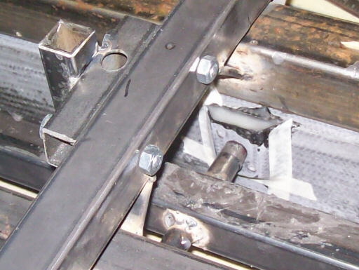
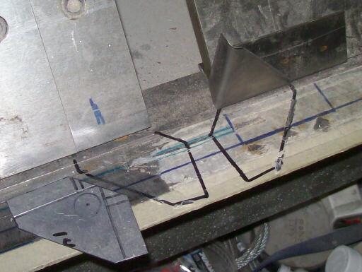
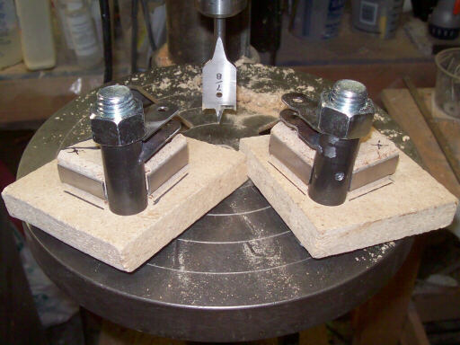
On 3 January, here's the finished travel stops jigged into place on the airbrake drive cranks and ready to go to the welder.
Homebuilt aviation is not for folks who don't try things at home.
page updated 3 January 2010 all text and graphics copyright (c) 2010 HP Aircraft,
LLC