Lots of little stuff going on up at the shop, but not many photos. The biggest thing I've done lately is to make a rack for holding rolls of composites and vacuum bagging materials. I welded it up out of 3" square steel tubing, and put it on castering wheels (two with brakes). Unfortunately, it was snowing when I finished it, so no photos. I was in a hurry to get the hell out of Arnold before the highway went chains-only.
One thing that I managed to do during the holiday break was to build a cycle-test machine and put about a hundred hours of test cycles on my proposed design for the high-radial-load push-pull guides.
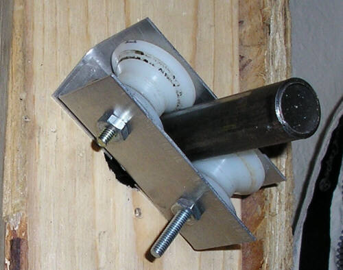
As you'll recall from my last Update, these guides are based on two little flanged rollers, with two ball bearings per roller. The machine has a 50 RPM gear motor turning a crank with 7/8" throw to move a push-pull tube back and forth 1.75" at the rate of 3000 times per hour. The push-pull tube is supported near each end with one of the proposed guides. The machine has a gas spring that applies a lateral force of 40 lbs to the middle of the push-pull tube. Since the spring is located more or less in the middle of the two guides, each guide is loaded with about 20 lbs of radial force. I arranged each guide in a different orientation to test different directions of radial loading.
Anhyow, I assembled the machine and ran it for 100 hours (at 50 RPM that's 300,000 cycles) to test the 0-degree and 90-degree orientations of the guides and noted only minor wear of the guide rollers.
I also performed a twenty-cycle test with the push-pull tube loaded with 180 lbs of lateral pressure (the gas spring's 40 lbs plus my 140 lbs of holiday-meal-supplemented body weight). Since the loading was applied near the middle of the push-pull tube, each guide was exposed to 90 lbs of radial force. The guide system survived this test with no breakage or even discernable wear.
A follow-on test will also apply 100 hours of 40-lb testing to the 45-degree orientation of the guide. I have to schedule that test around the weather, since the sound of the little 50 RPM gearmotor disturbs our dog so much that he won't sleep in the garage while it's running. We don't want poor Bear having to sleep out in the back yard when it's snowing.
Coming up, we're convening Session III of the Douglas Flat Akaflieg from 14 through 22 January 2006. Our plan is to make a couple of sets of fuselage shells, and bond them together. And in order for that to happen, Brad and I have been scrambling to put together all the little things we'll need to close the aft fuselages. I've been making parts for the tools for the push-pull tube guides (the low-radial-load linear ball bearings), and also collecting all of the materials for the pneumatic connections, rudder control connections, and antennas. Brad has been making tools and parts for a bunch of little fiberglass clips that will secure the cables and hoses in the aft fuselage. More photos of that stuff to come.
Here's the photos I do have on hand:
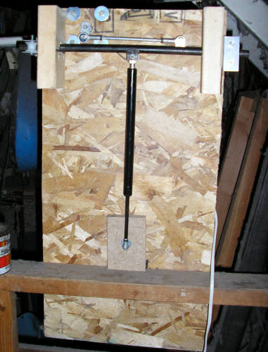
A general view of the wig-wag machine. The vertical tube is the body of a gas spring that applies 40 lbs of lateral force to the 5/8" horizontal push-pull tube. The push-pull tube is supported near each end by a roller guide. The push rod and two rod end bearings above the push-pull tube turn the rotary motion of the 7/8" gearmotor crank into reciprocating motion of the push-pull tube.
A view of the right guide, mounted in the 0-degree orientation.
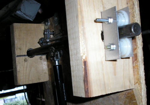
The left guide, mounted in the 90-degree orientation.
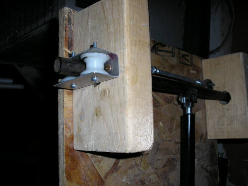
The right guide again, this time mounted in the 45-degree orinetation after the 300,000 cycle test.
page updated 4 January 2006 all text and graphics copyright (c) 2006 HP Aircraft, LLC