Brad's been working hard on the instrument pod tooling, and on tools for a couple smaller parts. It looks like he's about ready to make the molds for the instrument pod hood.
This weekend I made a jig for the forward roll bellcrank weldment, and kitted out parts so the TIG guy can zap together five of them. If my touch at welding was a bit better I'd weld them myself, but this stuff is mostly .035" wall 4130 steel tubing, and it's too easy to burn through it.
I also welded adjusters into the inboard aft edge of the lower right wing mold, and did a preliminary washout correction on the mold using the survey templates I made earlier. I'll sleep on it a couple days before I lock it in, though.
The photos:
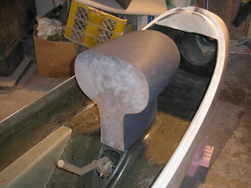
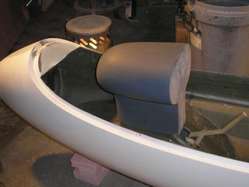
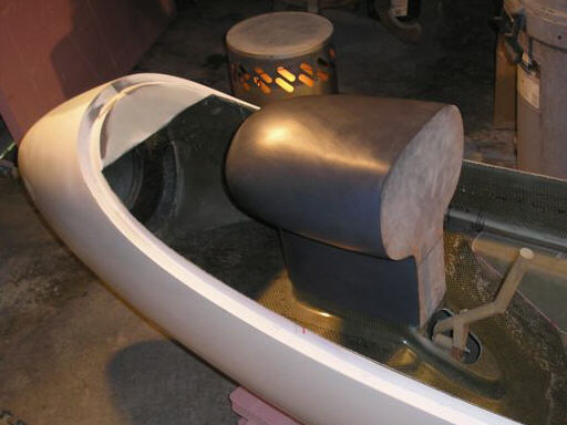
The instrument pod hood in flat Duratec spray primer.
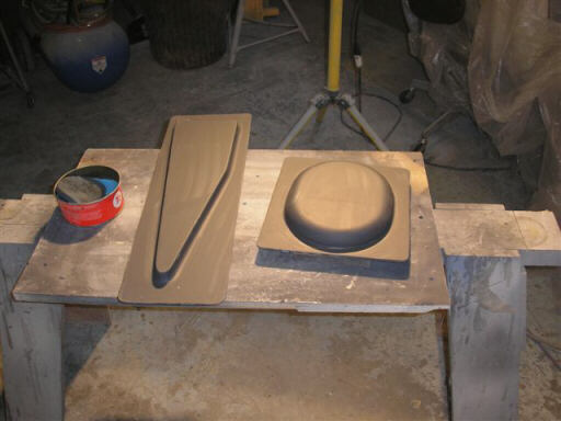
Molds for the tailwheel fender and for a forward floor interstitial stiffener. These will be male-molded parts, so Brad's gone straight from drawings to molds, no plugs necessary.
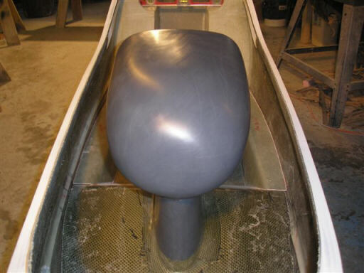
The instrument pod hood plug polished and waxed.
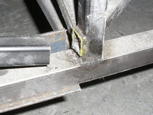
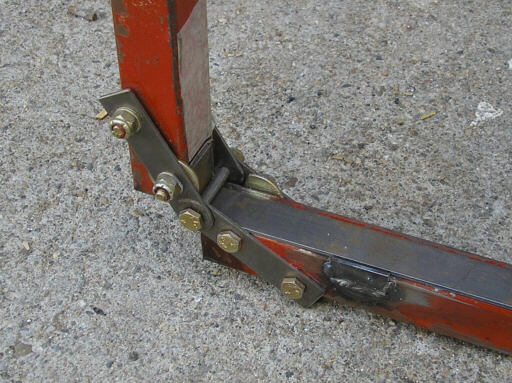
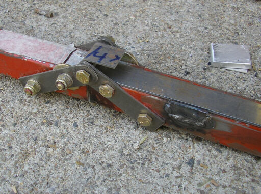
Down at the Arnold shop, here I've cut a 1" section out of one of the wing mold truss diagonals.
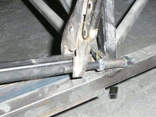
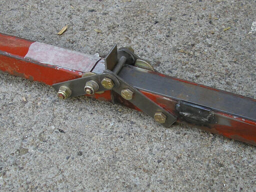
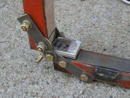
Clamping the adjuster in place.
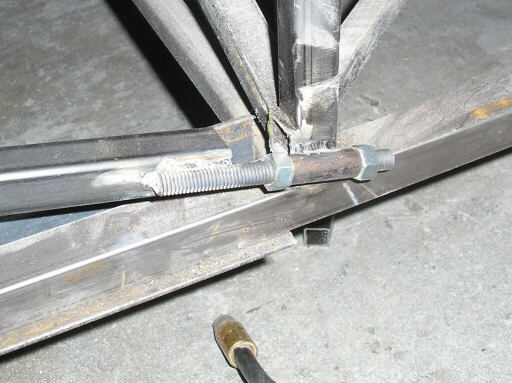
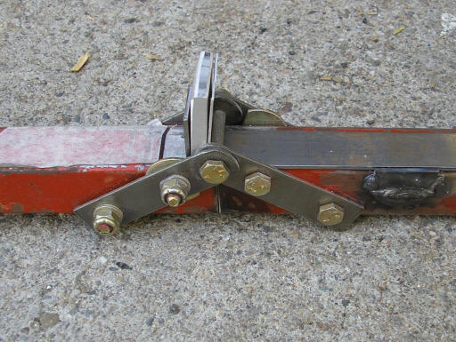
Welded and ready for adjusting.
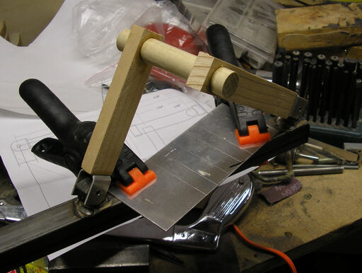
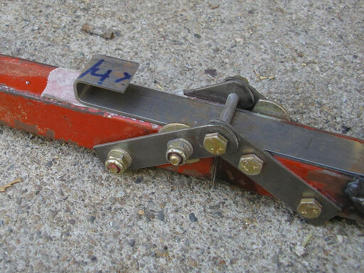
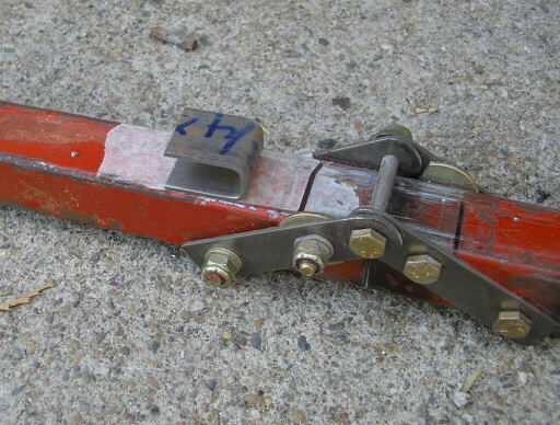
The start of the forward roll bellcrank jig. The blocks being clamped down are of thickness calibrated to match the forks on the horns of the bellcrank. The scribe lines come from the aluminum template in the background.
I've welded the fork locators in place and mounted a wooden mockup on them. The scribe lines on the template give me a visual alignment reference.
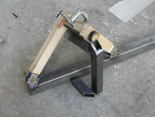
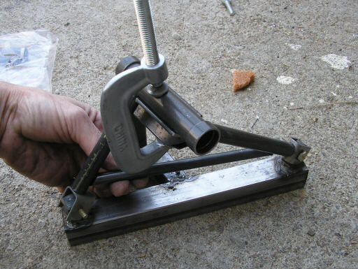
Here I'm making the jig feature that locates the vertical pivot tube of the bellcrank.
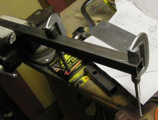
Here's a couple photos of a tool I made back when I was making center stick retrofit kits for HP-18. For reasons I don't entirely recall I call it a "horn doggie." I use it to make the forks that go at the ends of a bellcrank arm. Here its loaded with a strip of 3/4" wide, .063" thick 4130 steel.
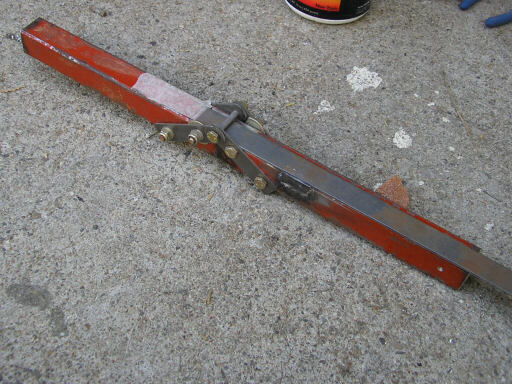
You crank one arm of the horn doggie.
And release, and you've got a nice clean bend in the steel strip. That much you can do with any brake.
Then you slide the strip through the tool a ways. I use this shim stack to get the distance right.
And crank the tool again.
Remove the shims (don't lose them).
Remove the strip from the tool.
Take it over to the shear and cut off a nice, even, square fork for a bellcrank arm.
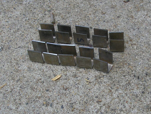
Here's the ten forks for the first five bellcranks. Half of them have an inside width of 7/16" for RE3M6-2N 20-ball rod ends, the other half have 9/16" inside width for HM-4 rod ends on high-displacement gimbal spacers.
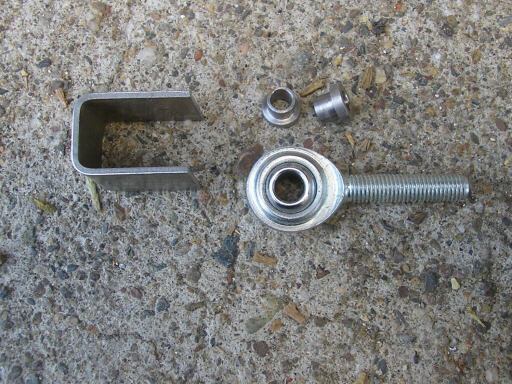
Here's an HM-4 rod end (actually a commercial -4) and a pair of those gimbal spacers. The ball width is 3/8", but if you clamp it directly in a 3/8" wide fork you only get about +/- 10.5 degrees of misalignment. Adding the gimbal spacers increases the maximum misalignment out to about 18 degrees. These spacers also allow the use of an AN3 bolt instead of AN4, which saves a bit of weight on the hardware.
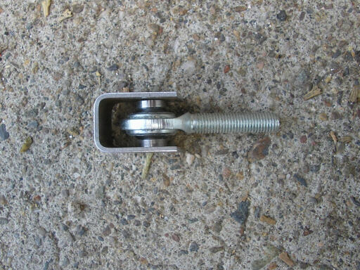
Here's the jig loaded with the first set of parts for the bellcrank.
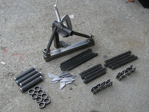
Here's the jig and all five sets of bellcrank parts.
Homebuilt aviation is not for folks who don't try things at home.
page updated 7 April 2008 all text and graphics copyright (c) 2008 HP Aircraft,
LLC