Before I can start laying up wing skins in my molds, I have to know where the spar is going to go inside the wings and translate that into tooling that locates the spar in the mold. That tooling places the spar in the right spot, and shows me where I have to place features that relate to the wing skins and the spar.
The most important aspect of locating the wing spar is where the spar stub protrudes from the inboard end of the wing. There, the spar relates not only to its wing, but to the opposite wing and to the fuselage as well. It also relates to the root rib, and to the lift pins as well.
Of course, I have a pretty good idea where the spar goes, that's all in the working drawings that I'm building the glider from. However, going from those two-dimensional working drawings to usable 3D geometries is not trivial. Add in the usual mix of deviations that you always get when working with hand-lofted shapes, and it can become a mess in a hurry.
All of this has been on my mind for literally a couple of years now. During that time, I've been mentally floundering around, trying to figure up the most effective and elegant way of jigging out the wing/spar/fuselage interface so that all the parts fit and everything is snug and happy. In the end, I decided that the easiest thing to do is to construct a full-size physical simulation of the interface, and use that as a jig for welding up the spar locating fixtures. I decided that since I (fingers crossed) don't need the fuselage or wing plugs any more, I'd construct the interface simulation out of parts of the plugs. And that's what we did this weekend.
Before we go further, yes, I carefully considered that I might need those plugs again in the future. I carefully weighed that against the benefits of easily constructing the interface simulation. What I decided was that, with two fuselages already out of the molds I could just as easily recreate the fuselage molds from those, and if it came down to needing new wing molds I'd just have them CNC cut. So, yeah, I thought about it. I also considered the possible historic value of the plugs. And decided in favor of just getting stuff done.
Anyhow, once the interface simulation is finished, the end product is a pair of wing stubs that I can fit back into the wing molds and weld up the spar stub and lift pin locating fixtures. I can probably also use them to locate parts of the auto-connecting controls, but that's still a ways off.
Besides that stuff, we also went up to Big Trees state park, just up the highway from the shop. I also did a bit more work on the airbrake boxes, and also used my hydraulic Break-o-Tron to pull-test some sun-bleached webbing I bootied off of a chockstone on the Caverns, just below Selaginella, in Yosemite.
Here's the photos. Sorry for the long download, but there's a lot of them:
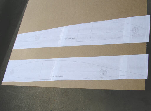
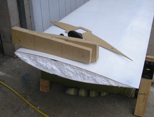
Here's the templates that show where the spar is supposed to go in relation to the interface plan and lift pin axes. There's a right and a left instead of two identical copies because of the way the right spar starts in front and trends aft towards the tip, and the way the left spar starts in back and trends forward towards the tip.
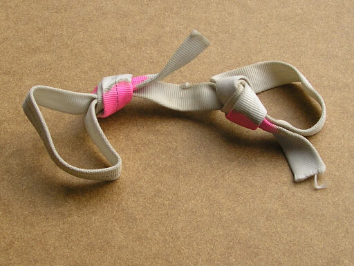
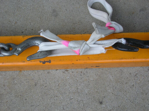
Here's that piece of webbing from the Caverns. There was just enough to tie two test loops, one with an overhand on a bight and the other with a ring bend (water knot). The pink areas were shaded from the sun inside the knot that secured it to the chockstone, and show the original color of the webbing. The white areas are where all the color was bleached out by the sun.
The separation curve for liberating the inboard end of the right wing plug.
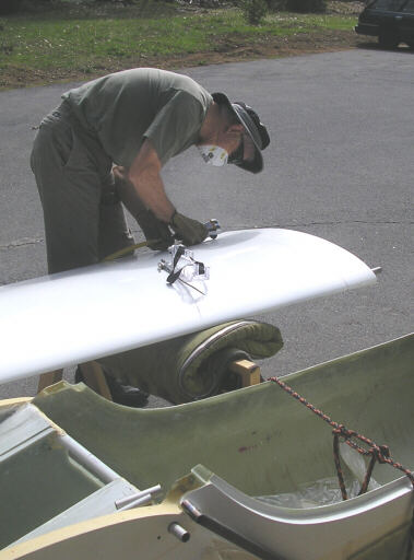
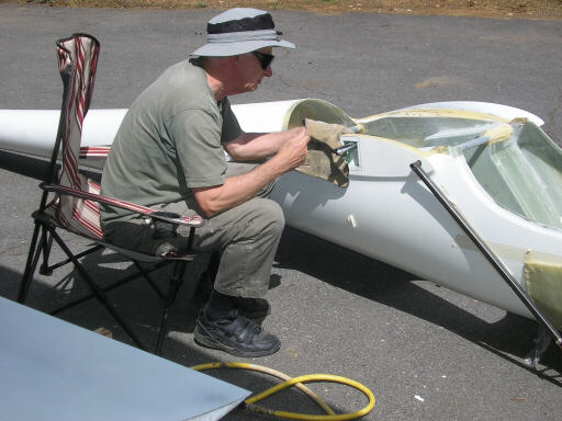
Doug gets to work with the die grinder.
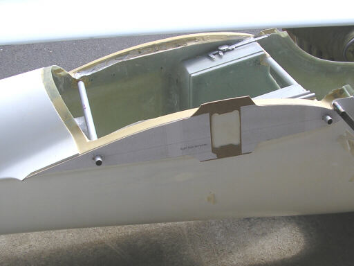
The partially finished right side template in place on the fuselage. Some day I'll invent a bandsaw blade that will get into closed holes like this.
Doug's done liberating the right stub, and moving on to the left.
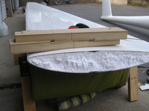
Here I've finished the template and marked out the spar hole.
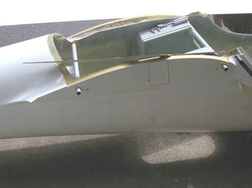
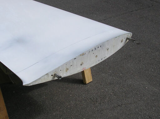
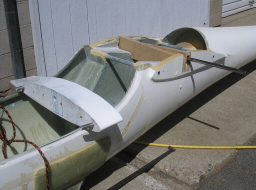
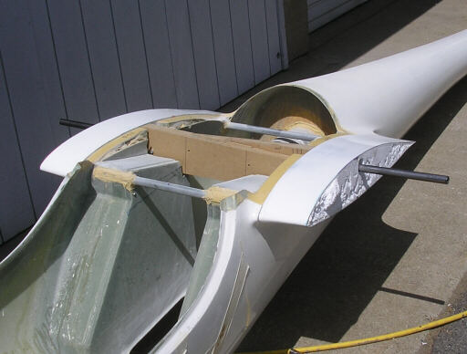
The right wing stub in place on the fuselage. These parts haven't been together since we glued the fairings onto the wing plugs with hot glue and popsicle sticks, but they still fit together perfectly. I was quite gratified to see that the finish work that Brad Hill did on the wing plugs perfectly preserved the tangency between the curves of the fuselage and wing portions of the interface fairing. Good job, Brad!
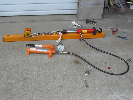
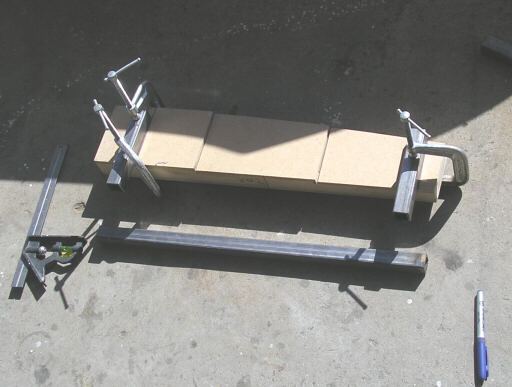
The Break-o-Tron ready for action. The hydraulic gauge shows pressure inside the pullback ram; multiplying that by the effective piston area of 1.153 in^2 gives force to within the +/- 2% accuracy of the guage.
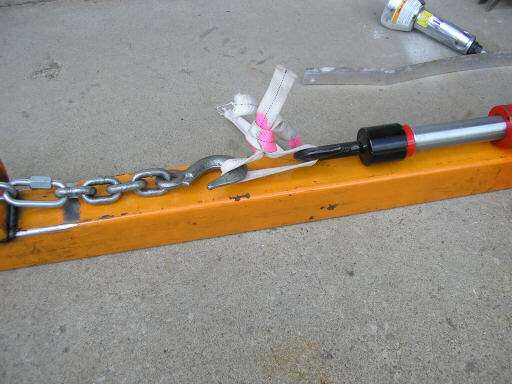
Water knotted sling, broken at 7.2kn (kilonewtons). When new, a tied loop in this material is typically good for about 23kn, so this chunk here is down to about 1/3 of its original strength.
Testing the overhand-on-a-bight loop.
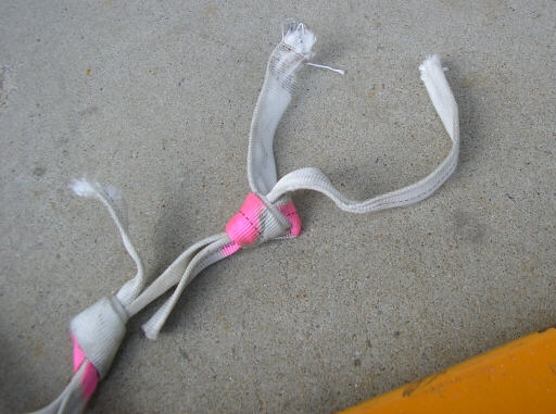
The overhand-on-a-bight loop broken at 8.6kn. I really expected this loop to have a lower breaking strenght than the other, since the overhand on a bight pulls the webbing around tighter corners inside the knot. Puzzling.
Doug tunnels through the fuselage.
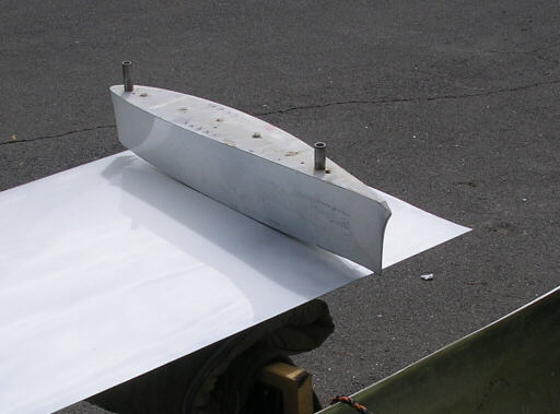
The raw end of the wing plug, and also the pair of spar stub mockups. I made these in Steve Smith's garage over the last couple of Thursdays. I decided that was better than cutting the ends off of my first-article wing spars.
Note the "stair steps" in the mating faces of the stubs. That's where stacks of the Graphlite carbon stop. The steps in the real spars ramp off more gradually, at about a 20-degree angle, but I saw no need to embody that in these mockups.
Here's the male molds for the airbrake boxes. Still under construction.
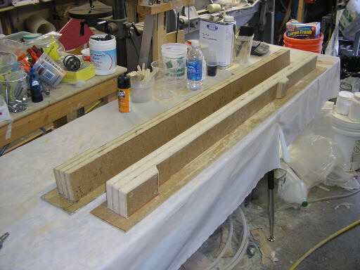
Starting to jig out the fixture that locates the spar. I wanted to get just this couple of welds done before attaching the spar stub to the wing plug stub.
Doug decks off the cut ends of the wing plug stubs.
Here the spar stub pair is fitted into the fuselage, and the left stub has its attachment spindle glued in place. The wing plug stub is rough-bored for the spindle.
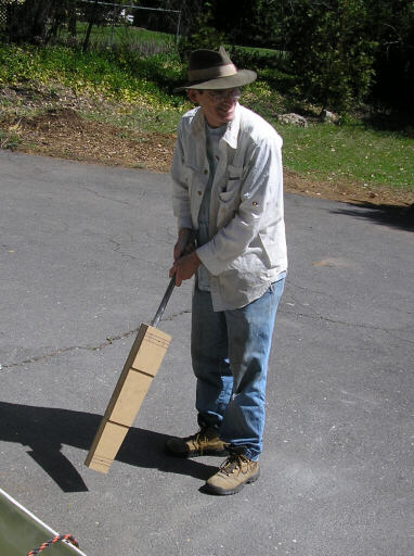
I looked at the left spar stub and thought, if only I'd made it of oak it would have made a great cricket bat.
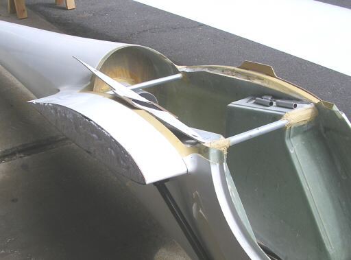
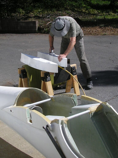
Here the wing plug stubs and spar stub pair are in place. Now the only thing left is to attach the spar stubs to their respective wing plug stubs, and then separate them. We did actually do that later in the afternoon, after our walk in Big Trees.
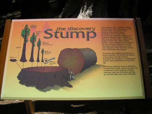
I've seen this poor thing a dozen times or more, and it still cracks me up in a sad way. "Hey, here's a magnificent tree, the tallest and most massive we've ever seen. Let's cut it down!"
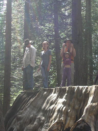
Me, Doug, and the kids on the Stump. This thing is huge, for a while there was a dance hall built on it.
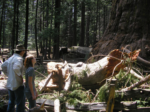
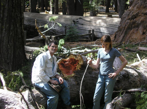
This thing that Alia and I are admiring is not a fallen tree. It is a branch, fallen from the tree in the background.
Homebuilt aviation is not for folks who don't try things at home.
page updated 8 April 2007 all text and graphics copyright (c) 2007 HP Aircraft,
LLC