The last weekend of February, I unbagged the layups we did on the wing plug outboard sections the previous weekend and prepared them for their bottom skins. The left one looked great, but the right one had picked up a handful of forward sweep that concerned me some.
The error that I observed would have made absolutely no noticable difference in the structural, aerodynamic, or even aeroelastic properties of the aircraft. We're talking about somewhere near 1/4" of deviation from a straight line. But ooh, it rankled me some. When you sight down the leading edge of a wing, you expect to see something like a straight line, or at least straight segments - excepting the odd Spitfire, of course. For a one-off wing, I would have ignored it. But no way was I going to make molds that embodied a whoopsie like that.
In general, when it comes to non-structural issues of exterior profile, I try to observe what I have come to call the "one-pixel rule." That is, if I superimposed the intended outline on the actual outline, and then printed both on an 8.5" x 11" sheet of paper with a 300 dpi laser printer, the two outlines would not deviate from each other by more than one pixel width. That gives me about 0.2" (5mm) to work with.
In practice, it is actually very hard to sight down the leading edge of a glider. The normal sag from 1g parking loads will cause several inches of deflection at the tip, meaning that you're more like finding the plane of an arc than finding the axis of a line.
Anyhow, the problem that I had pretty much came equipped with its own solution. The sweep was pretty much concentrated near the section break between cores 4R and 5R. So I just cut through the fiberglass top skin (the bottom was still unskinned) near the section break, built a traction device out of wood blocks and attached it to the trailing edge spanning the cut. Then I just cranked up and down on the traction device until the leading edge was straight. When I was satisfied, I locked the traction device with a C-clamp, trenched the cut to about a 12:1 tooling scarf, and then laid in four ply of fiberglass tape. I laid that onto its bed to cure, and when I returned on 6 March it was straight enough for me. After grinding down the scarf joint exterior, it was ready for the next steps.
The weekend of 6/7 March, Doug Gray came back up to the shop for what we hope is the last long weekend of layups. We laid up and bagged the bottom skins for both the straightened right outboard plug section on Saturday, and returned on Sunday and did the same for the already-straight-enough left outboard wing plug. As I mentioned previously, we did these kind of upside-down from the way we did the inboard bottm skins. Starting from the top and working down to the tabletop, the layup stack had:
10. 12" x 12" x 2" concrete paving stones for weight
9. Cardboard (to protect the vac bag from sharp corners on stones)
8. Vacuum bag sheet
7. Top shuck
6. Wing plug core
5. Fiberglass laminations
4. Mylar surfacing sheet
3. Vacuum bag sheet
2. Bottom shuck
1. Tabletop
Basically, atmospheric pressure on the vacuum bag forces the layup up against the bottom of the core. The top shuck is there inside the bag to help form the leading edge treatment and to give a platform for weighting. The bottom shuck cradles the assembly where it meets the table, and the stones hold the assembly against the table for good straightness.
On Monday 8 March 2004, Doug Gray and I parted ways at Columbia airport (o22) at 5:20 am. There, I got onto a Cessna 206 for my carpool ride into the Silicon Valley, and Doug headed south towards Tehachapi with the aft fuselage plug tied to the top of his van. The plan is for Precomtec R+D to align the aft fuselage plug onto the first-article forward fuselage, and then to use my rough sketches to invent the missing 70" or so of fuselage surface that occurs between the forward fuselage and the aft fuselage plug.
This update's photos:
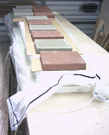
Here's the right outboard wing plug bagged up so the bottom skin can cure. The 6R on the end of the bottom shuck stands for core section 6 (the most outboard one), Right side. The faint blue mark to the right of the 6R designation is the chordwise station of maximum depth, where the carbon stiffeners go. The milky film is the vacuum bag (just 4 mil poly sheeting from the hardware store). The heavy black line on the poly sheet is vacuum bag sealing tape, one of the few "real" vacuum bagging supplies I use on these big tooling layups.
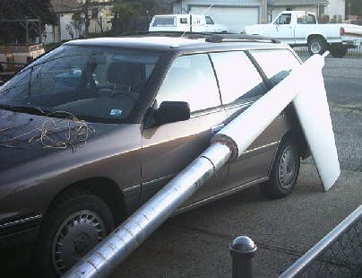
Here the aft fuselage plug reclines against my Soob snow car while Doug and I prepare to tie it onto the top of his van. The aluminum boom is the same RS-15 tailboom that shows up in the earliest project photos as the forward fuselage spindle tube. On the hood of the Soob is a tangle of telephone wire that Alia and I later used to make an electromagnet as part of an impromptu Sunday-evening science project. Using a 6-volt lantern battery that Doug loaned us for a few minutes, we could easily pick up items of steel AN hardware with the magnet.
Next weekend, I'm not doing anything on the HP-24 project except maybe unbagging the left outboard wing plug section. Saturday I'm watching the kids, and Sunday we're driving into the bay area to catch some community theater and maybe do some V1+ bouldering and 5.9 wall climbs.
page updated 8 March 2004 all text and graphics copyright (c) 2004 HP Aircraft, LLC