Last weekend I applied the carbon shear sleeve to the stubs of both of Brad's wing spars. I also fiddled around with the flaperon hinge pivots, the new tailwheel fender form, and the production-standard canopy hinge pivot. Next weekend I'll probably try to take the kids on a hike and start making the locating clamps that we'll use to fit the spars into the wing mold spiders.
Up in Monroe, Brad has been fitting his Tost nose release, seat back, and forward lift tube. He's also done some filling around the canopy separation curve, we'll likely have photos of that next time.
The photos:
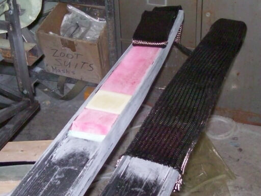
Cutting the plies of carbon sleeving to length on the spar stubs. Because this stuff is braided on the bias, the only way to get the length right is to cinch it down onto whatever you're sleeving and cut it in place.
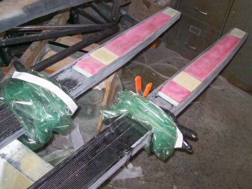
The spar stubs ready for sleeving, with the vacuum bags in place.
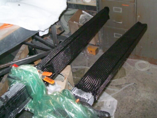
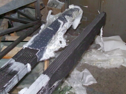
With the layers of sleeve saturated.
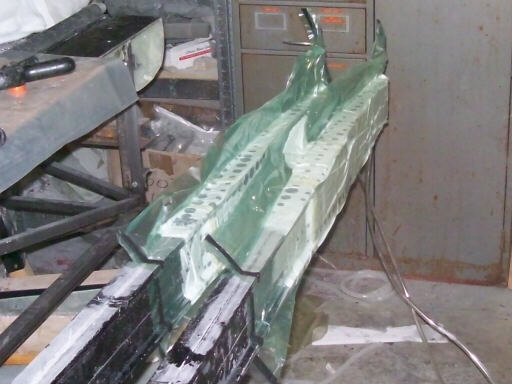
Bagged down.
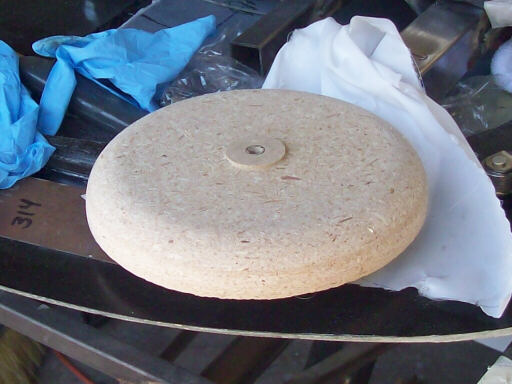
The latest tailwheel fender form, fresh from the lathe. We had one of these, but it only made one part. This time I will make a temporary mold off of it, make a new form off of that temporary mold, and then use that form as a male mold for the fender parts.
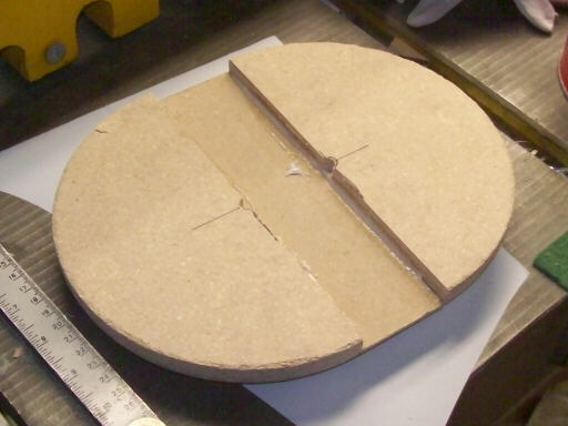
Here I've cut the cake into two halves and bonded a 2" plug in the middle with micro and 5-minute epoxy.
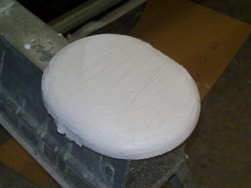
Painted with polyester spray primer thickened with microballoons.
The next day, the spar stubs are unbagged and almost ready to install. First I will drill 1/4" holes at the sites for the inboard wing pins.
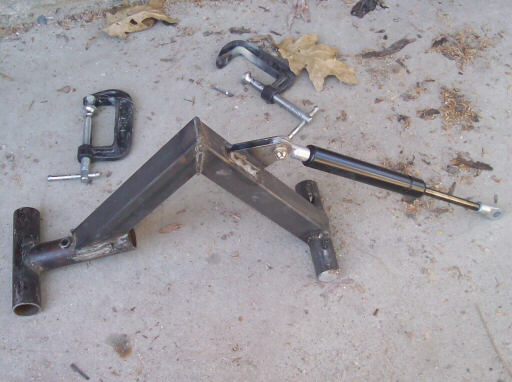
The mockup of the canopy pivot arm, which I used to refine the gas spring geometry. That piece of aluminum plate has a hole in it for a bolt that I attached the top of the gas spring to. I just clamped the plate onto the arm and played around with the geometry until the hold-open force felt about right and the opening angle was adequate. Then I used the aluminum plate to position a steel leaf that I welded onto the arm, and finally I used that first leaf to position a second leaf that I also welded in place.
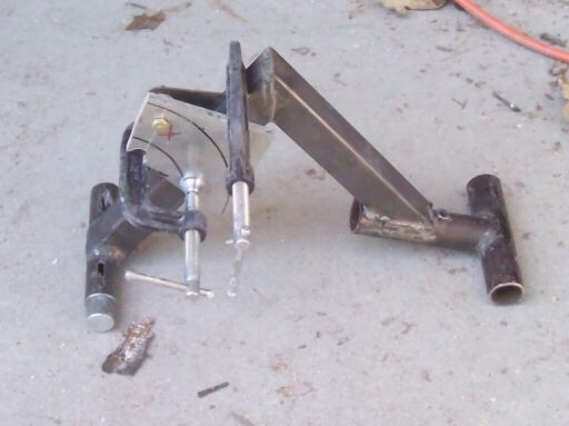
The arm with the leaves for the gas spring welded in place.
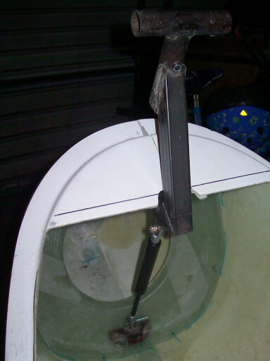
The arm mounted in the fuselage.
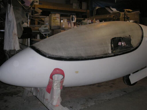
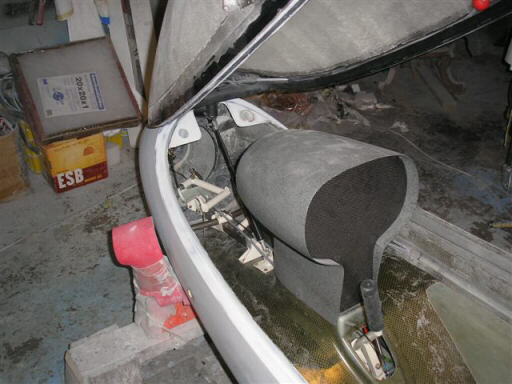
Brad's fuselage, with his new canopy sliding window in place. This thing looks just like a real sailplane!
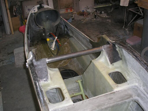
Brad's cockpit.
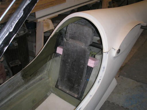
Brad's seat back. The kit standard will probably be something that pins any of a row of holes in the side angles to adjust for different pilot heights.
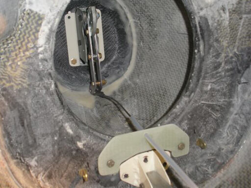
Brad's Tost tow hitch and release cable. Note also the clevis bolts that will anchor the forward ends of the rudder cables ahead of where they go through the serpentine tubes on the rudder pedals. I still intend to offer the Schreder 455 tow hitch as a low cost alternative to the $500 Tost hitch. Robert Mudd pretty near blew a gasket when I suggested that on r.a.s; his position seems to be that I shouldn't trust sailplane kit builders to fabricate a tow hitch on their own. My experience with the legacy HPs and with the RV-series airplanes suggests otherwise. My experience with Tost wheels and brakes suggests that sometimes Tost does a worse job of fabricating glider parts than homebuilders do.
The forward lift tube that Brad has bonded and taped in place with multiple plies of fiberglass and carbon.
Homebuilt aviation is not for folks who don't try things at home.
page updated 9 April 2009 all text and graphics copyright (c) 2009 HP Aircraft,
LLC